- NXP Forums
- Product Forums
- General Purpose MicrocontrollersGeneral Purpose Microcontrollers
- i.MX Forumsi.MX Forums
- QorIQ Processing PlatformsQorIQ Processing Platforms
- Identification and SecurityIdentification and Security
- Power ManagementPower Management
- MCX Microcontrollers
- S32G
- S32K
- S32V
- MPC5xxx
- Other NXP Products
- Wireless Connectivity
- S12 / MagniV Microcontrollers
- Powertrain and Electrification Analog Drivers
- Sensors
- Vybrid Processors
- Digital Signal Controllers
- 8-bit Microcontrollers
- ColdFire/68K Microcontrollers and Processors
- PowerQUICC Processors
- OSBDM and TBDML
-
- Solution Forums
- Software Forums
- MCUXpresso Software and ToolsMCUXpresso Software and Tools
- CodeWarriorCodeWarrior
- MQX Software SolutionsMQX Software Solutions
- Model-Based Design Toolbox (MBDT)Model-Based Design Toolbox (MBDT)
- FreeMASTER
- eIQ Machine Learning Software
- Embedded Software and Tools Clinic
- S32 SDK
- S32 Design Studio
- Vigiles
- GUI Guider
- Zephyr Project
- Voice Technology
- Application Software Packs
- Secure Provisioning SDK (SPSDK)
- Processor Expert Software
-
- Topics
- Mobile Robotics - Drones and RoversMobile Robotics - Drones and Rovers
- NXP Training ContentNXP Training Content
- University ProgramsUniversity Programs
- Rapid IoT
- NXP Designs
- SafeAssure-Community
- OSS Security & Maintenance
- Using Our Community
-
-
- Home
- :
- Model-Based Design Toolbox (MBDT)
- :
- Model-Based Design Toolbox (MBDT)
- :
- Weird error with blockset on HW. Critical fault if not fixed.
Weird error with blockset on HW. Critical fault if not fixed.
- Subscribe to RSS Feed
- Mark Topic as New
- Mark Topic as Read
- Float this Topic for Current User
- Bookmark
- Subscribe
- Mute
- Printer Friendly Page
Weird error with blockset on HW. Critical fault if not fixed.
- Mark as New
- Bookmark
- Subscribe
- Mute
- Subscribe to RSS Feed
- Permalink
- Report Inappropriate Content
Hi,
I am getting some very weird results when running my application code on my S32K148EVB.
I have my CAN receive blocks that read 80 messages on CAN2. This contains voltage data 176 cells this is then put into a 16x11 matrix of cells. I find the min and max including the index by using the following MATLAB function:
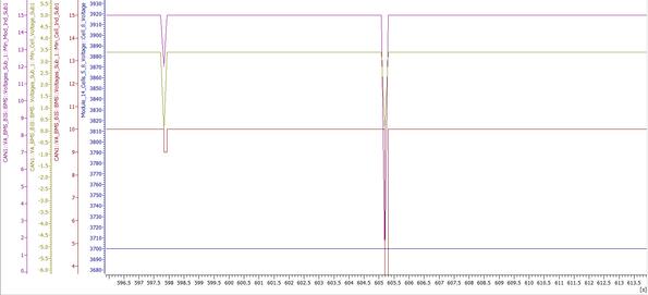
The issue I am seeing is the value for Min cell volt seems to flash to 0V a lot throughout runtime. I am using CANalyzer to send the CAN messages containing cell voltage so I know that the minimum cell is a solid 3.4v continuously.
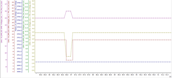
Occasionally it's for more than 1 CAN sample time, for example it happens here for 3 steps with is 300ms overall:
Sometimes the output goes to 3.2V, but only ever those 2 values, 0V and 3.2V:
What could be causing this? I really need help on this as have the wrong voltage that much really isn't good. My guess is that the CAN receive is some how malfunctioning. I also transmit the total sum of all cell voltages coming straight in from CAN and that also drops lower when this dip happens, therefore has to be something to do with that surely?
I have attached my model.
Thanks in advance!
- Mark as New
- Bookmark
- Subscribe
- Mute
- Subscribe to RSS Feed
- Permalink
- Report Inappropriate Content
Hello @Poley ,
I had a look at your model but I cannot generate code because of some dependencies missing. However, because the code from 1 is executed on interrupt, while the code for 2 is executed every 0.005 seconds, the step time, and also the order of the generated code could be different from the order you expect to get the code generated, I would expect to see that at the Tn to get data handled from the Tn-1 and at some point, the data to not be available and the minimum to be applied on 0 arrays. I am glad that by changing some blocks you now are not seeing the 0 values.
Regarding the external mode, seems to be an issue with the communication. Does the generated code ends on the board and it is successfully flashed? I wonder if there is some resource like UART or GPIO shared with the External Mode communication (UART).
Regards,
Marius
Regarding the external mode,
- Mark as New
- Bookmark
- Subscribe
- Mute
- Subscribe to RSS Feed
- Permalink
- Report Inappropriate Content
The code flashes and runs. Am I doing it right?
I click on "Hardware" tab and the select this button:
Then select Control Panel -> Connect and that's where it fails.
I can't see what could be blocking the communication?
Thanks!
- Mark as New
- Bookmark
- Subscribe
- Mute
- Subscribe to RSS Feed
- Permalink
- Report Inappropriate Content
Looks like it was my triggered CAN receive block. I had it separate which block to run by message buffer. Taking the time and making 85 CAN trigger blocks for each individual ID seems to fix the issue. Not 100% sure why and not sure why external mode still doesn't work.
- Mark as New
- Bookmark
- Subscribe
- Mute
- Subscribe to RSS Feed
- Permalink
- Report Inappropriate Content
Also @mariuslucianand Could you please have a quick look as to why this model doesn't work in external mode? I get the following error:
The model runs in external if I just have some LED logic set up but doesn't with the current logic in, I don't understand why it wouldn't.
Thanks!


