
- NXP Forums
- Product Forums
- General Purpose MicrocontrollersGeneral Purpose Microcontrollers
- i.MX Forumsi.MX Forums
- QorIQ Processing PlatformsQorIQ Processing Platforms
- Identification and SecurityIdentification and Security
- Power ManagementPower Management
- MCX Microcontrollers
- S32G
- S32K
- S32V
- MPC5xxx
- Other NXP Products
- Wireless Connectivity
- S12 / MagniV Microcontrollers
- Powertrain and Electrification Analog Drivers
- Sensors
- Vybrid Processors
- Digital Signal Controllers
- 8-bit Microcontrollers
- ColdFire/68K Microcontrollers and Processors
- PowerQUICC Processors
- OSBDM and TBDML
-
- Solution Forums
- Software Forums
- MCUXpresso Software and ToolsMCUXpresso Software and Tools
- CodeWarriorCodeWarrior
- MQX Software SolutionsMQX Software Solutions
- Model-Based Design Toolbox (MBDT)Model-Based Design Toolbox (MBDT)
- FreeMASTER
- eIQ Machine Learning Software
- Embedded Software and Tools Clinic
- S32 SDK
- S32 Design Studio
- Vigiles
- GUI Guider
- Zephyr Project
- Voice Technology
- Application Software Packs
- Secure Provisioning SDK (SPSDK)
- Processor Expert Software
-
- Topics
- Mobile Robotics - Drones and RoversMobile Robotics - Drones and Rovers
- NXP Training ContentNXP Training Content
- University ProgramsUniversity Programs
- Rapid IoT
- NXP Designs
- SafeAssure-Community
- OSS Security & Maintenance
- Using Our Community
-
-
- Home
- :
- Model-Based Design Toolbox (MBDT)
- :
- Model-Based Design Toolbox (MBDT)
- :
- Re: Issue with MC33771B MBDT SPI Config.
Issue with MC33771B MBDT SPI Config.
- Subscribe to RSS Feed
- Mark Topic as New
- Mark Topic as Read
- Float this Topic for Current User
- Bookmark
- Subscribe
- Mute
- Printer Friendly Page
- Mark as New
- Bookmark
- Subscribe
- Mute
- Subscribe to RSS Feed
- Permalink
- Report Inappropriate Content
Dear @mariuslucianand
I have a question regarding configuration the MC33771B blocks.
I have the S32K144 with x3 SPI connected to x3 chipset of MC33771B via difference SPI 0~2.
When I tried to config to intialize this BCC config.
It is only allowed for single-block.
Can you help advise me how to config the MDBT to communicate with 3-SPI
(3-Chipsets of MC33771B independently)
Thank you,
Marius
Solved! Go to Solution.
- Mark as New
- Bookmark
- Subscribe
- Mute
- Subscribe to RSS Feed
- Permalink
- Report Inappropriate Content
Hello @Narudol-T
I've made an analysis based on the information you've provided and as I've told you in my first reply, the current approach of code generation in MBDT only allows you to have one device connected over the SPI or up to 15 connected over TPL.
MBDT generates code on top of the MC3377xB driver and here, the main Driver configuration uses the bcc_drv_config_t structure type which keeps the state only for one device in SPI mode.

Now, the MBDT MC3377xB_Config_Block generates only one structure in each model, so from here comes the limitation. If it were to support more devices over SPI, we would have to generate this for every block. We designed such blocks considering that if an application would use more BCCs than one it will use the TPL approach.
Now, your approach is not impossible and obviously, it can be achieved in MBDT but requires an important amount of changes in the current implementation, which can not be provided via a simple HotFix to you. Basically, you request here a new feature.
I see two options for you:
1. Start using custom code. With this approach, you can insert C code based on the BCC driver and fill the bcc_drv_config_t structures for each SPI instance. You can find a good starting point in this article: https://community.nxp.com/t5/NXP-Model-Based-Design-Tools/How-to-use-your-own-C-code-in-our-Toolbox-...
2. You open a request to NXP, to implement the support of this kind of functionality. For that, you have to contact your NXP local FAE and he/she will then contact the Manager who handles MBDT. This can be a long process but in the end, you will have this functionality implemented in our Toolbox.
Hope this helps,
Marius
- Mark as New
- Bookmark
- Subscribe
- Mute
- Subscribe to RSS Feed
- Permalink
- Report Inappropriate Content
Thank you so much for the helpful post.
- Mark as New
- Bookmark
- Subscribe
- Mute
- Subscribe to RSS Feed
- Permalink
- Report Inappropriate Content
Hello @Narudol-T ,
You are right, MBDT current implementation only allows to generate code for only one Cell controller over SPI protocol. Currently, it is not possible to control more than 1 BCC over SPI.
When you want to connect more packs to one MCU you should consider using the TPL approach, because with that you can connect up to 14 MC33771B to the same MCU. This uses a daisy chain isolated communication between the Cell Packs and the MC33771B controller.
When you use the MC33771B SPI communication, the GND of the battery pack is connected through the MC33771B to the MCU GND. If you want to connect more than one battery pack to the same MCU over SPI, all the packs should have the same GND otherwise you will end up with some electrical issues there.
Can you detail your setup? Do you want to connect the packs in serial or parallel?
Hope this helps,
Marius
- Mark as New
- Bookmark
- Subscribe
- Mute
- Subscribe to RSS Feed
- Permalink
- Report Inappropriate Content
Dear @mariuslucianand
Because we have prior reason regard communication that we must using CAN Bus for stability.
In order to reduce cost, the SPI with multiple BCC will be the best options for us at the moment.
Unfortunately, our team already proceed the hardware to sample B2 level.
We are using SPI isolator chip x3pcs from Analog devices to separate the ground.
Since the customer's usage application may reach at 1,415Vdc.
So we already consider the BCC to be isolated grounding in every BCCs,
If you may look at below hardware, the above area are BCC x3 sets (42cells)
and coming after with Isolators (LED, SPI, Power Supplies) x3sets.
And then S32K144 with comm ports x3CAN & x1RS485.
Can you help how should I modify the software to get this hardware working for x3-SPI?
Thank you,
Narudol T.

- Mark as New
- Bookmark
- Subscribe
- Mute
- Subscribe to RSS Feed
- Permalink
- Report Inappropriate Content
Hello @Narudol-T ,
Thank you for sharing part of your design with us! It looks pretty cool and you have a very nice design there!
So you have already foreseen the GND problem and you have isolated each BCC on the MCU using ADUMs.
I have one more question before analyzing the options and recommend the one that will fit your needs the best: I've seen in the attached schematic how it looks for the B1. Have you connected all of them to the same SPI0 instance and have assigned one ChipSelect signal for each BCC (B1 - SPI0/CS0, B2 - SPI0/CS1, B3 - SPI0/CS2)? Or have you assigned one entire SPI instance for each BCC? Basically (B1 - SPI0, B2 - SPI1, B3 - SPI2)
Are you planning to design the entire application using MBDT for S32K in Matlab and Simulink?
Waiting for your reply,
Marius
- Mark as New
- Bookmark
- Subscribe
- Mute
- Subscribe to RSS Feed
- Permalink
- Report Inappropriate Content
Dear @mariuslucianand
Sorry for not missing one question.
yes, we are planning to generate *.S19 file frrom MATLAB for flashing via CAN Bus to pre-set bootloader in S32K.
Thank you,
Narudol T.
- Mark as New
- Bookmark
- Subscribe
- Mute
- Subscribe to RSS Feed
- Permalink
- Report Inappropriate Content
Dear @mariuslucianand
We before once want to use single SPI for x3 BCCs.
however, when we digged down into schematics design.
we found that the supply power of SPI isolator chip will be common ground which lead to isolation problem.
so we need to allocate separated SPI one for each BCC with totally separated power supplies.
Thank you,
Narudol T.
- Mark as New
- Bookmark
- Subscribe
- Mute
- Subscribe to RSS Feed
- Permalink
- Report Inappropriate Content
Hello @Narudol-T
I've made an analysis based on the information you've provided and as I've told you in my first reply, the current approach of code generation in MBDT only allows you to have one device connected over the SPI or up to 15 connected over TPL.
MBDT generates code on top of the MC3377xB driver and here, the main Driver configuration uses the bcc_drv_config_t structure type which keeps the state only for one device in SPI mode.
Now, the MBDT MC3377xB_Config_Block generates only one structure in each model, so from here comes the limitation. If it were to support more devices over SPI, we would have to generate this for every block. We designed such blocks considering that if an application would use more BCCs than one it will use the TPL approach.
Now, your approach is not impossible and obviously, it can be achieved in MBDT but requires an important amount of changes in the current implementation, which can not be provided via a simple HotFix to you. Basically, you request here a new feature.
I see two options for you:
1. Start using custom code. With this approach, you can insert C code based on the BCC driver and fill the bcc_drv_config_t structures for each SPI instance. You can find a good starting point in this article: https://community.nxp.com/t5/NXP-Model-Based-Design-Tools/How-to-use-your-own-C-code-in-our-Toolbox-...
2. You open a request to NXP, to implement the support of this kind of functionality. For that, you have to contact your NXP local FAE and he/she will then contact the Manager who handles MBDT. This can be a long process but in the end, you will have this functionality implemented in our Toolbox.
Hope this helps,
Marius
- Mark as New
- Bookmark
- Subscribe
- Mute
- Subscribe to RSS Feed
- Permalink
- Report Inappropriate Content
Understood, basically i need to insert C code here and hoping NXP will release new feature into MDBT later.
Thank you very much!!
Narudol T.
- Mark as New
- Bookmark
- Subscribe
- Mute
- Subscribe to RSS Feed
- Permalink
- Report Inappropriate Content
Hello @Narudol-T ,
That is correct! But you can reduce the waiting time by requesting this functionality to NXP.
Regards,
Marius
- Mark as New
- Bookmark
- Subscribe
- Mute
- Subscribe to RSS Feed
- Permalink
- Report Inappropriate Content
Sorry for troubling again & again.
I have requested to Hongkong Supporting NXP Team who helped me design this hardware.
Meanwhile I need to demo the hardware before it goes to C1 samples process.
(Mass Production Trial Sample version no.1)
So, I am trying your C-Code based provided in your link.
However, I have encountered same problem with @rathi_tg
(Sorry that I am not fluent in Coding, I am mostly hardware engineer before this year.)
Even I tried to read the countermeasure you sugguested in that articles, I cannot understand well.
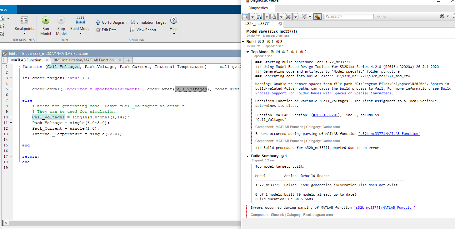
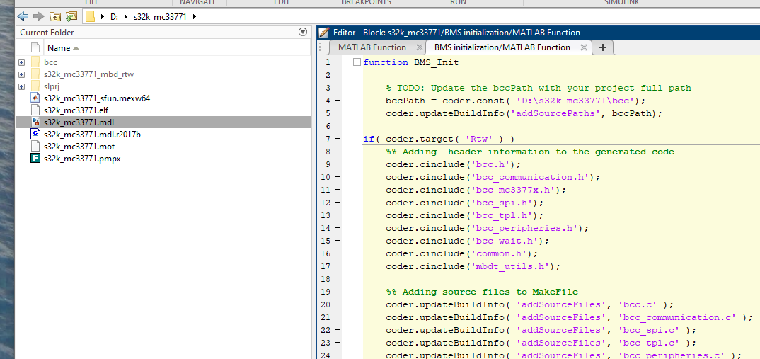
Can you little more explain how to solve this "cell_Voltages..." issue again ?
Thank you in advanced & looking forward to you reply.
Narudol T.
- Mark as New
- Bookmark
- Subscribe
- Mute
- Subscribe to RSS Feed
- Permalink
- Report Inappropriate Content
To overcome this problem, in this work a passive balancing system design The MC33771 is a Li-Ion battery cell controller IC designed for automotive and Support standard SPI and transformer isolated daisy chain communication with of the battery with the configuration of the excellent performance so that the charging.