- NXP Forums
- Product Forums
- General Purpose MicrocontrollersGeneral Purpose Microcontrollers
- i.MX Forumsi.MX Forums
- QorIQ Processing PlatformsQorIQ Processing Platforms
- Identification and SecurityIdentification and Security
- Power ManagementPower Management
- MCX Microcontrollers
- S32G
- S32K
- S32V
- MPC5xxx
- Other NXP Products
- Wireless Connectivity
- S12 / MagniV Microcontrollers
- Powertrain and Electrification Analog Drivers
- Sensors
- Vybrid Processors
- Digital Signal Controllers
- 8-bit Microcontrollers
- ColdFire/68K Microcontrollers and Processors
- PowerQUICC Processors
- OSBDM and TBDML
-
- Solution Forums
- Software Forums
- MCUXpresso Software and ToolsMCUXpresso Software and Tools
- CodeWarriorCodeWarrior
- MQX Software SolutionsMQX Software Solutions
- Model-Based Design Toolbox (MBDT)Model-Based Design Toolbox (MBDT)
- FreeMASTER
- eIQ Machine Learning Software
- Embedded Software and Tools Clinic
- S32 SDK
- S32 Design Studio
- Vigiles
- GUI Guider
- Zephyr Project
- Voice Technology
- Application Software Packs
- Secure Provisioning SDK (SPSDK)
- Processor Expert Software
-
- Topics
- Mobile Robotics - Drones and RoversMobile Robotics - Drones and Rovers
- NXP Training ContentNXP Training Content
- University ProgramsUniversity Programs
- Rapid IoT
- NXP Designs
- SafeAssure-Community
- OSS Security & Maintenance
- Using Our Community
-
-
- Home
- :
- Model-Based Design Toolbox (MBDT)
- :
- Model-Based Design Toolbox (MBDT)
- :
- Re: How to Disable I/O Pins Not High-Z By Default?
How to Disable I/O Pins Not High-Z By Default?
- Subscribe to RSS Feed
- Mark Topic as New
- Mark Topic as Read
- Float this Topic for Current User
- Bookmark
- Subscribe
- Mute
- Printer Friendly Page
- Mark as New
- Bookmark
- Subscribe
- Mute
- Subscribe to RSS Feed
- Permalink
- Report Inappropriate Content
Hello:
If we want to use I/O pins hat are not high-Z by default for a different purpose (for example, for LPSPI1_PCS0, see row 67 in the worksheet below) how do we do that in NXP MBDT?
If I try to assign the pin "PTD3" for that purpose, it doesn't work.
That specific pin (and many others) are used by the FRDMDUAL33664EVB evaluation board, which we are using in conjunction with S32K144, a board-pair designed to work together, which suggests there must be a way.
Any suggestions?
Thanks
Solved! Go to Solution.
- Mark as New
- Bookmark
- Subscribe
- Mute
- Subscribe to RSS Feed
- Permalink
- Report Inappropriate Content
I discovered in S32DS the "Pin Mux" setting lets us choose the ALT3 signal mapping to PTD3 for the multiplexer, see below. Is there a way to do this when generating an application in MBDT? Or, do we need to load the project into S32DS where this setting can be changed, in order for LPSPI1_PCS0 to be able to connect to PTD3?
- Mark as New
- Bookmark
- Subscribe
- Mute
- Subscribe to RSS Feed
- Permalink
- Report Inappropriate Content
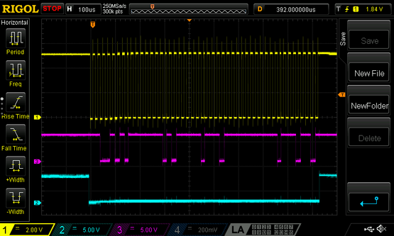
I was able to get SPI Master to work through pins used by the FRDMDUAL33664EVB evaluation board:
TPL1TXDATA PTB16/LPSPI1_SOUT
TPL1TXSCLK PTB14/LPSPI1_SCK
TPL1+2TXCSB PTD3
Confirmed with an oscilloscope:
And similarly, was able to see the 48-bit message propagate onto the TPL wire pair.
It may be that help from other questions contributed to getting through this problem.
- Mark as New
- Bookmark
- Subscribe
- Mute
- Subscribe to RSS Feed
- Permalink
- Report Inappropriate Content
Hello @rsating ,
In MBDT we do not offer support for selecting the muxing GPIO settings, just because we don't have such component like PEX, the one that you show in the last screenshot, something like a dedicated pin muxing block.
Instead of that, we check to have each pin assigned to a single peripheral only, and we generate the pins C code initialization with settings for that peripheral. All our peripherals config blocks, have a 'Pins' drop down selection, from which you can select the desired pin and that block will generate assign the Alt mux option directly in C code.
For example, all the hardware CS pins of the SPI blocks, can be assigned from the LPSPI_Config block. The drop down options will be displayed dynamically with options available for the selected instance. If you want to use the PD3 as CS0 for the LPSPI 1, you have to select the PD3 as PCS0.
This will automatically generate in the C code the mux that you are looking for.
For the BMS TPL Communication, we have an article on the Community, https://community.nxp.com/t5/NXP-Model-Based-Design-Tools/BMS-amp-MBDT-MC33771B-MC33772B-TPL-communi... describing the scenario that you are interested in, alongside with example.
Hope this helps,
Marius


