
- NXP Forums
- Product Forums
- General Purpose MicrocontrollersGeneral Purpose Microcontrollers
- i.MX Forumsi.MX Forums
- QorIQ Processing PlatformsQorIQ Processing Platforms
- Identification and SecurityIdentification and Security
- Power ManagementPower Management
- MCX Microcontrollers
- S32G
- S32K
- S32V
- MPC5xxx
- Other NXP Products
- Wireless Connectivity
- S12 / MagniV Microcontrollers
- Powertrain and Electrification Analog Drivers
- Sensors
- Vybrid Processors
- Digital Signal Controllers
- 8-bit Microcontrollers
- ColdFire/68K Microcontrollers and Processors
- PowerQUICC Processors
- OSBDM and TBDML
-
- Solution Forums
- Software Forums
- MCUXpresso Software and ToolsMCUXpresso Software and Tools
- CodeWarriorCodeWarrior
- MQX Software SolutionsMQX Software Solutions
- Model-Based Design Toolbox (MBDT)Model-Based Design Toolbox (MBDT)
- FreeMASTER
- eIQ Machine Learning Software
- Embedded Software and Tools Clinic
- S32 SDK
- S32 Design Studio
- Vigiles
- GUI Guider
- Zephyr Project
- Voice Technology
- Application Software Packs
- Secure Provisioning SDK (SPSDK)
- Processor Expert Software
-
- Topics
- Mobile Robotics - Drones and RoversMobile Robotics - Drones and Rovers
- NXP Training ContentNXP Training Content
- University ProgramsUniversity Programs
- Rapid IoT
- NXP Designs
- SafeAssure-Community
- OSS Security & Maintenance
- Using Our Community
-
-
- Home
- :
- Product Forums
- :
- MPC5xxx
- :
- Threshold high/Period Mode, Reaction module 2, MPC5746R, setup issues.
Threshold high/Period Mode, Reaction module 2, MPC5746R, setup issues.
- Subscribe to RSS Feed
- Mark Topic as New
- Mark Topic as Read
- Float this Topic for Current User
- Bookmark
- Subscribe
- Mute
- Printer Friendly Page
Threshold high/Period Mode, Reaction module 2, MPC5746R, setup issues.
- Mark as New
- Bookmark
- Subscribe
- Mute
- Subscribe to RSS Feed
- Permalink
- Report Inappropriate Content
Hi
I'm using the Reaction module 2 (MPC5746R) to control an actuator. I want to use the (44.6.5 Threshold high/Period Mode) to get a fixed switching period, I have calculated the Period prescaler rate value (PERPRESC) and Period time value (PER), according to below, but the reality and my calculations doesn't match.. In reality it just doesn't work. (See attached image1).
Module clock = 200MHz --> 0,005us/clock cycle.
PERPRESC = 0
PER = 9999
Period time = 0,005 * (PER + 1) * (PERPRESC+1)
Period time = 0,005 * 10000 * 1
Period time = 50us
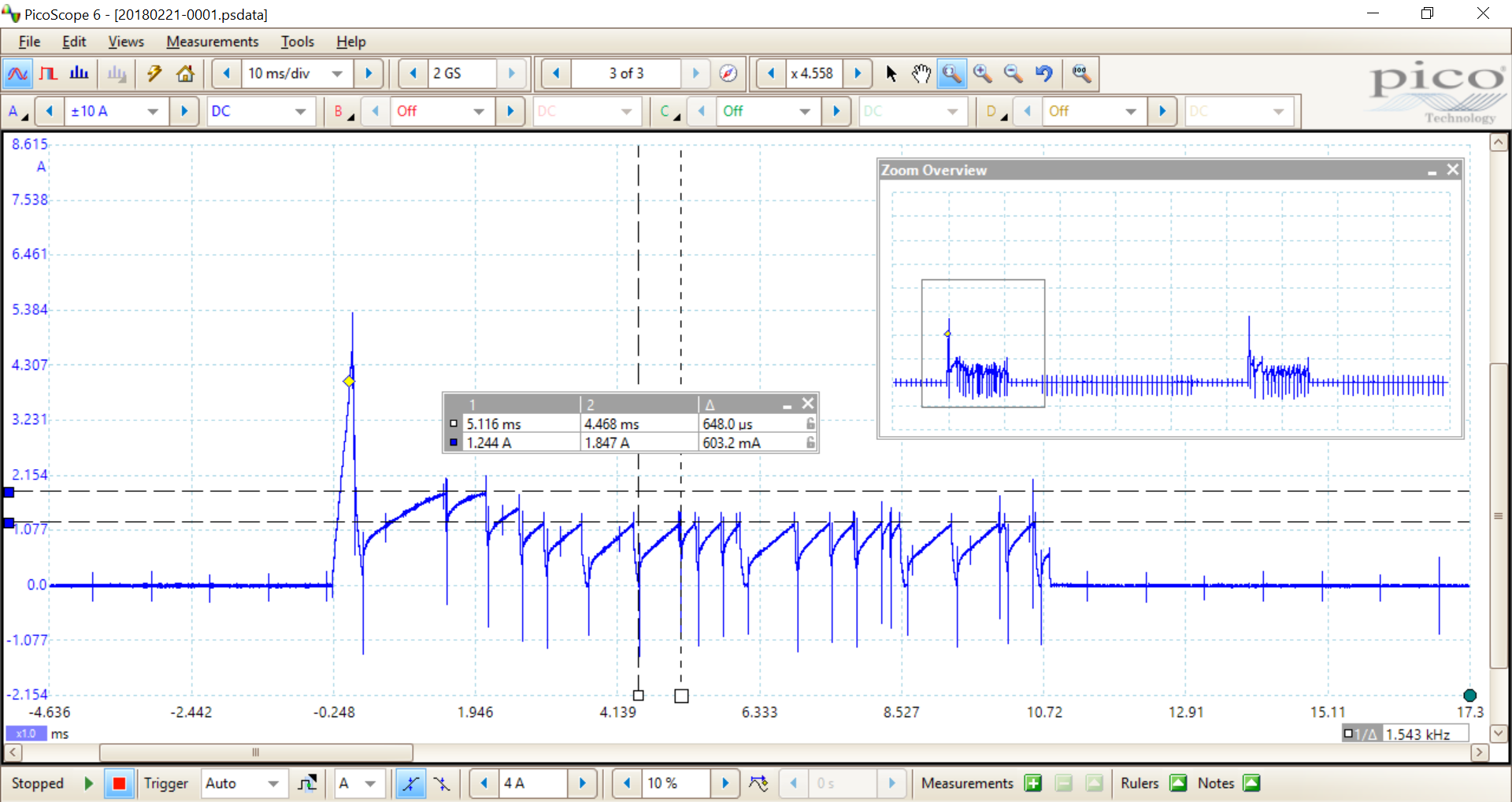
I have found a setting that resembles something similar to what I'm looking for (PER = 99, PERPRESC = 0), but the period is just not fixed.. (See attached image2). What have I missed? (I have used 44.6.2 Threshold/Hold-off Mode until now, so I know the rest of the module works well.)
REACM2_INIT_T reacm2_module_setup =
{
/* MCR init */
FS_REACM2_MDIS_ENABLE
| FS_REACM2_TPREN_ENABLE
| FS_REACM2_HPREN_ENABLE,
/* TCR init */
FS_REACM2_HPRE(4)
| FS_REACM2_TPRE(8),
/* THRR init */
FS_REACM2_WREN1_DISABLE
| FS_REACM2_WREN0_DISABLE,
/* PCR init */
FS_REACM2_PERPRESC(0) // no division
| FS_REACM2_PER(99), // period generator
/* PSCR init */
FS_REACM2_DLY(0), // no delay between the period pulses of the consecutive channel
/* ADCMAX init */
FS_REACM2_ADCMAX(0), //when set to 0 the adc max limit checking disabled
/* RANGE_PWD init */
FS_REACM2_RANGE_PWD(0), // no pwd range checking is performed
/* MIN_PWD init */
FS_REACM2_MIN_PWD(0) // no minimum pulse width checking is performed
};
/* threshold and time definitions */
THRESHOLD_T thsPeakH = {0xF63, NAN}; //4,8A (0xF63)
THRESHOLD_T thsPeakL = {0x000, NAN}; //NA
THRESHOLD_T thsHold1H = {0x5C5, NAN}; //1,8A (0x5C5) //2,5A (0x803)
THRESHOLD_T thsHold1L = {0x000, NAN}; //NA
THRESHOLD_T thsHold2H = {0x3D8, NAN}; //1,2A (0x3D8) --> avg. ~1A
THRESHOLD_T thsHold2L = {0x000, NAN}; //NA
SH_TIME_T stmPeak = {0x0000, NAN}; //NA
SH_TIME_T stmHold1 = {0xF800, NAN}; //~2,5ms (0xF800)
SH_TIME_T stmHold2 = {0x0000, NAN}; //NA
HOLD_TIME_T htmPeak = {0x000, NAN}; //NA
HOLD_TIME_T htmHold1 = {0x000, NAN}; //NA ~6us (0x140)0x855
HOLD_TIME_T htmHold2 = {0x000, NAN}; //NA ~6us (0x140)0x855
/* modulation word parameters definition */
MODULATION_WORD_T mod_phases [3] =
{
/* Loop, Ioss, MM, SM, HOD C, HOD B, HOD A, LOD C, LOD B, LOD A, THRESPT H, THRESPT L, STPT, HDOFFTPT */
{FS_REACM2_LOOP_OFF, FS_REACM2_IOSS_HOD, FS_REACM2_MM_TT, FS_REACM2_SM_THRESHOLD_EVENT, FS_REACM2_HOD_C_HIGH, FS_REACM2_HOD_B_HIGH, FS_REACM2_HOD_A_HIGH, FS_REACM2_LOD_C_HIGH, FS_REACM2_HOD_B_HIGH, FS_REACM2_LOD_A_HIGH, &thsPeakH, &thsPeakL, &stmPeak, &htmPeak},
{FS_REACM2_LOOP_OFF, FS_REACM2_IOSS_HOD, FS_REACM2_MM_TLOWP, FS_REACM2_SM_TIMER_EVENT, FS_REACM2_HOD_C_LOW, FS_REACM2_HOD_B_HIGH, FS_REACM2_HOD_A_HIGH, FS_REACM2_LOD_C_LOW, FS_REACM2_LOD_B_HIGH, FS_REACM2_LOD_A_LOW, &thsHold1H, &thsHold1L, &stmHold1, &htmHold1},
{FS_REACM2_LOOP_ON, FS_REACM2_IOSS_HOD, FS_REACM2_MM_TLOWP, FS_REACM2_SM_NO_TRANSITION, FS_REACM2_HOD_C_LOW, FS_REACM2_HOD_B_HIGH, FS_REACM2_HOD_A_HIGH, FS_REACM2_LOD_C_LOW, FS_REACM2_LOD_B_HIGH, FS_REACM2_LOD_A_LOW, &thsHold2H, &thsHold2L, &stmHold2, &htmHold2}
};
Thank you in advance
//Emil
- Mark as New
- Bookmark
- Subscribe
- Mute
- Subscribe to RSS Feed
- Permalink
- Report Inappropriate Content
I have been able to use the threshold / period mode. I ditched the Freescale example code as I found it made the module more complicated (for me). Setting the registers directly was easier to understand.
I seem to recall being unsure on the size of a timer tick too, although once set it was repeatable.
James