
- Forums
- Product Forums
- General Purpose MicrocontrollersGeneral Purpose Microcontrollers
- i.MX Forumsi.MX Forums
- QorIQ Processing PlatformsQorIQ Processing Platforms
- Identification and SecurityIdentification and Security
- Power ManagementPower Management
- Wireless ConnectivityWireless Connectivity
- RFID / NFCRFID / NFC
- Advanced AnalogAdvanced Analog
- Neural Processing UnitsNeural Processing Units
- MCX Microcontrollers
- S32G
- S32K
- S32V
- MPC5xxx
- Other NXP Products
- S12 / MagniV Microcontrollers
- Powertrain and Electrification Analog Drivers
- Sensors
- Vybrid Processors
- Digital Signal Controllers
- 8-bit Microcontrollers
- ColdFire/68K Microcontrollers and Processors
- PowerQUICC Processors
- OSBDM and TBDML
- S32M
- S32Z/E
-
- Solution Forums
- Software Forums
- MCUXpresso Software and ToolsMCUXpresso Software and Tools
- CodeWarriorCodeWarrior
- MQX Software SolutionsMQX Software Solutions
- Model-Based Design Toolbox (MBDT)Model-Based Design Toolbox (MBDT)
- FreeMASTER
- eIQ Machine Learning Software
- Embedded Software and Tools Clinic
- S32 SDK
- S32 Design Studio
- GUI Guider
- Zephyr Project
- Voice Technology
- Application Software Packs
- Secure Provisioning SDK (SPSDK)
- Processor Expert Software
- Generative AI & LLMs
-
- Topics
- Mobile Robotics - Drones and RoversMobile Robotics - Drones and Rovers
- NXP Training ContentNXP Training Content
- University ProgramsUniversity Programs
- Rapid IoT
- NXP Designs
- SafeAssure-Community
- OSS Security & Maintenance
- Using Our Community
-
- Cloud Lab Forums
-
- Knowledge Bases
- ARM Microcontrollers
- i.MX Processors
- Identification and Security
- Model-Based Design Toolbox (MBDT)
- QorIQ Processing Platforms
- S32 Automotive Processing Platform
- Wireless Connectivity
- CodeWarrior
- MCUXpresso Suite of Software and Tools
- MQX Software Solutions
- RFID / NFC
- Advanced Analog
- Neural Processing Units
-
- NXP Tech Blogs
- RSS フィードを購読する
- トピックを新着としてマーク
- トピックを既読としてマーク
- このトピックを現在のユーザーにフロートします
- ブックマーク
- 購読
- ミュート
- 印刷用ページ
- 新着としてマーク
- ブックマーク
- 購読
- ミュート
- RSS フィードを購読する
- ハイライト
- 印刷
- 不適切なコンテンツを報告
Hi,
I'm currently working on a custom bootloader application for the MPC5604BxLQ microcontroller,
which is on the TRK-MPC5604B Board.
As an IDE I am using Codewarrior for MCU Version 10.5 on Windows 7 64-bit professional.
The goal of the bootloader application is to be able to store up to 3 different applications in the
codeflash (512KB CodeFlash), that can be executed by the bootloader.
The layout of the codeflash should look like this in the end:


I limit the application size at 110KB for the moment (an AppSlots is about 125KB).
So far I am able to receive arbitrary binary files (UART) and write the binary data to a
selected AppSlot with its starting address. I verified the written data by using the memory
browser while debugging the bootloader application.
Furthermore I created an application, that does some LED blinking by using an
interrupt timer (PIT) or by simply polling a timer (decided by a define directive).
Let's call this application the test-app.
-------------------------------------------------
Some background information:
-------------------------------------------------
During my bachelor thesis I implemented a bootloader application for the STM32F4-microcontroller
by STMicroelectronics. Back then I used an application note, as
well as an example project regarding In-Application-Programming by STMicroelectronics as a starting point.
In the end it came down to this:
1) For the test-app:
- tell the linker to build for the starting address of the intended AppSlot
(back then it meant to change the linker address from 0x08000000 to 0x08010000 in the IDE CoIDE)
- right after entering the main routine of the test-app, offset the interrupt vector table to 0x08010000
2) For the bootloader (the actual jump to the test-app):
- disable all interrupts
- jump to the test-app by doing the following routine (pretty much taken from the example by ST)
// Prepare the Jump_To_Application()-function
id (*Jump_To_Application)(void);
uint32_t JumpAddress = *(volatile uint32_t *)(APP_SLOT_START_ADDRESS + 4);
Jump_To_Application = (void(*)(void))JumpAddress;
// Init test-app's Stack Pointer
__set_MSP(*(volatile uint32_t *) APP_SLOT_START_ADDRESS);
// Jump to the test-app
Jump_To_Application();
(to this day I am not entirely sure why the JumpAddress is offset by 4)
// __set_MSP(...) was a library function
/** \brief Set Main Stack Pointer
This function assigns the given value to the Main Stack Pointer (MSP).
\param [in] topOfMainStack Main Stack Pointer value to set
*/
static __INLINE void __set_MSP(uint32_t topOfMainStack)
{
register uint32_t __regMainStackPointer __ASM("msp");
__regMainStackPointer = topOfMainStack;
}
--------------------------------------------------------------------------
With the background of my bachelor thesis I assumed that implementing a bootloader application on this specific controller
would not be that different.
------------------------------------------------------------------------------------------------------
So right now I need to solve the following two tasks for this project:
------------------------------------------------------------------------------------------------------
1) Alter and build the test-app for a specific AppSlot (let's say AppSlot 1).
2) Launch the flashed test-app using the bootloader.
-------------------------
What I did so far:
-------------------------
regarding 1)
- Setting the linker to build the test-app for AppSlot 1:
I looked at the linker control file (.lcf), which is provided by creating a project with the project wizard of codewarrior.
In particular the one for running an application in FLASH. In the memory section, I offset every entry by 0x00020000.
The resulting file is shown in attachment 1.
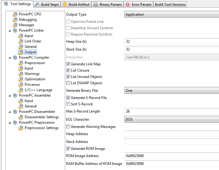
Furthermore I offset the "ROM Image Address" and "RAM Buffer Address of ROM Image" by 0x00020000 as well.
The result can be seen in attachment 2.
The test-app built fine with these settings and a binary was output.
- offsetting the interrupt vector table:
I could not find anything on this in the reference manual, so I don't know how this would be done.
But I'm fairly sure that something has to be done about this, as the vector table of the bootloader application
needs to be seperate of the one of a flashed application.
regarding 2)
- The actual JumpAddress is not really clear to me.
Is there an offset needed relative to the starting address of AppSlot 1?
- Furthermore I'm not entirely sure on why or where the stack pointer is moved, let alone on how one would do it in this case for this controller.
It may very well be that I'm completely overlooking something or doing something wrong.
In general the flashed applications need to be fully independant of the bootloader once they have taken over.
I am asking these questions as I can't progress.
I could not find application notes or other documentation on this matter regarding this controller.
Some help would be greatly appreciated!
BTW: I'm doing this project as part of my master degree (not the actual thesis). Furthemore this is my first project on a freescale controller, so I don't consider myself an expert.
Original Attachment has been moved to: attachment_1_MPC5604B_FLASH_AppSlot_1.lcf.zip
解決済! 解決策の投稿を見る。
- 新着としてマーク
- ブックマーク
- 購読
- ミュート
- RSS フィードを購読する
- ハイライト
- 印刷
- 不適切なコンテンツを報告
Hello Marcus,
Regarding your bootloader questions:
1) Setting the linker to build the test-app for AppSlot 1: you correctly set up the .lcf file + ROM image address in order to link your test application into App Slot 1 memory segment.
You can check the generated srecord .mot or .map file that the addresses fit the segment well.
- offsetting the interrupt vector table:
I assume you use the default FLASH project generated by the BareBoard project wizard as a template. The default project includes startup with interrupt controller initialization which also sets up the IVOR (Interrupt Vector Offset Register) to match with the start adress of exception_handlers memory section. So once the execution of TestApp reaches main() the value of IVOR should be 0x0002_1000 (this is address where your exception branch table for TestApp is placed).
2) Launch the flashed test-app using the bootloader:
Since your TestApp application is probably based on FLASH build configuration generated by BareBoard Wizard the "resetvector" section contains RCHW (Reset Conguration Half Word) + Reset Vector.
See below the snippet of .map file that illustrates the content of this section:
.__bam_bootarea section layout
Starting Virtual File
address Size address offset
---------------------------------
00000000 000008 00020000 00000240 1 .__bam_bootarea MPC5604B_init_flash_c.obj
00000000 000004 00020000 00000240 4 bam_rchw MPC5604B_init_flash_c.obj
00000004 000004 00020004 00000244 4 bam_resetvector MPC5604B_init_flash_c.obj
The reset vector start address = TestApp entry point is located at offset +4. You should therefore jump at address located at App Slot 1 + 0x4.
See MPC5604B reference manual for more information about RCHW and reset vector.
Hope it helps.
Stan
- 新着としてマーク
- ブックマーク
- 購読
- ミュート
- RSS フィードを購読する
- ハイライト
- 印刷
- 不適切なコンテンツを報告
Hi Markus
I have implemented an application with a bootLoader and two images (base image and an application image) on a Kinetis MK10.
You have to do following steps.
1. locate the bootloader and the application images within linker setting to the predefined addresses. You have to locate the vector table within Linker setting too. As example you can see how I did it with the IAR linnker settings for the base image at 0x800. By the way, I have an additionally ImageMapInfo with size 0x100 placed at 0x800. I use the entries in this range for the decision which image to run.
| define symbol __FlashConfig_start__ | = 0x00000400; | /* flash config fixed at 0x400 in kinetis */ | |||||
| define symbol __FlashConfig_end__ | = 0x0000040f; |
/* place the image map informations to the start of the image within */
/* fix memory placement with aid of linker !!! */
| define symbol __ImageMapInfo_start__ = 0x00000800; | /* non standard due to flash config */ |
| define symbol __intvec_start__ = __ImageMapInfo_start__ + 0x100; | /* must be a multiple of 0x100 */ |
/*-Memory Regions-*/
define symbol __region_FLASH_start__ = 0x00000000;
| define symbol __region_ROM_start__ | = __intvec_start__; |
| define symbol __region_ROM_end__ | = __region_FLASH_start__ + (10*1024)-1; /* 8kB defined by Monitor flash map */ |
| define symbol __region_RAM_start__ | = 0x20000000 - (4*1024); | /* 8kB limited through MK10DN32VFM5 */ | ||
| define symbol __region_RAM_end__ | = 0x20000000 + (4*1024)-1; |
/* split placement of stack and rest of RAM to ensure stack is at start of RAM ! */
place in RAM_region { block CSTACK };
place in RAM_region { readwrite, block HEAP };
...
2. In the BoolLoader you have to decide which application to run and then set the vector table register in the CPU and jump to the start of the program. As example you can see how I did it in my project with the MK10.
/// <summary>
/// checkToRun
/// This method checks if the provided images start code is set.
/// If the code is set, the method starts the image within branch to it.
/// If the code is not set, the method returns false
/// </summary>
bool checkToRun(CFlashMemoryMap::SMMtImageType image) {
// check for start code
if (gFlashMap.isImageProgrammed(image)) {
// valid start code is programmed -> set vector table to image
NVIC_SetVectorTable(NVIC_VectTab_FLASH, gFlashMap.getImageVectorOffset(image));
uint32_t vectorTable = SCB->VTOR;
__disable_interrupt(); // disable interrupts during jump
// jump into application image program, get address of __iar_program_start
// from vector table. Pointer to __iar_program_start is available in the
// 2nd entry of the vector table. (offset #4Bytes)
// following assembler instructions evaluates the address of
// __iar_program_start and branchses to __iar_program_start
asm("ADD %0,%0,#0x4 \n" // get address of VT into Rx and Add offset #4.
// Rx now holds a pointer to __iar_program_start.
"LDR %0,[%0] \n" // load address of __iar_program_start from Rx
// Rx now points to __iar_program_start.
"BX %0 \n" // branch to __iar_program_start
: : "r"(vectorTable)); // parameter list for asm instruction
}
return false;
}
/// <summary>
/// main
/// This is the main entry for the BooLoader application.
/// </summary>
uint32_t main (void) {
// first check for application to run
//------------------------------------------------------------------
if (!checkToRun(CFlashMemoryMap::SMMeAppImage)) {
// no valid Application image is programmed
// -> check for valid base image
if (!checkToRun(CFlashMemoryMap::SMMeBaseImage)) {
// error, no image available
}
}
return 1;
}
I hope it helps.
- 新着としてマーク
- ブックマーク
- 購読
- ミュート
- RSS フィードを購読する
- ハイライト
- 印刷
- 不適切なコンテンツを報告
Thank you for your post Arnold!
Unfortunately your solution is for a different controller.
to 1)
Your linker settings are quite a bit different than the one I have by creating a new project with the project wizard of codewarrior.
I need some clarification on why the memory sections are split up the way they are and what I need to consider when offsetting some of them for an application that is compiled for a different flash section.
to 2)
Neither do I have a VTOR register, nor a function like NVIC_SetVectorTable(...) for setting a new vector table.
I guess this function is part of some kind of library you are using, similar to the one I used with the STM32F4 controller.
I could find some discussions on this forum on bootloader matters, but sadly none regarding a MPC56xx - controller.
I actually need some specific advice for this controller / controller-family on how to achieve a solution to my problem.
- 新着としてマーク
- ブックマーク
- 購読
- ミュート
- RSS フィードを購読する
- ハイライト
- 印刷
- 不適切なコンテンツを報告
Hello Marcus,
Regarding your bootloader questions:
1) Setting the linker to build the test-app for AppSlot 1: you correctly set up the .lcf file + ROM image address in order to link your test application into App Slot 1 memory segment.
You can check the generated srecord .mot or .map file that the addresses fit the segment well.
- offsetting the interrupt vector table:
I assume you use the default FLASH project generated by the BareBoard project wizard as a template. The default project includes startup with interrupt controller initialization which also sets up the IVOR (Interrupt Vector Offset Register) to match with the start adress of exception_handlers memory section. So once the execution of TestApp reaches main() the value of IVOR should be 0x0002_1000 (this is address where your exception branch table for TestApp is placed).
2) Launch the flashed test-app using the bootloader:
Since your TestApp application is probably based on FLASH build configuration generated by BareBoard Wizard the "resetvector" section contains RCHW (Reset Conguration Half Word) + Reset Vector.
See below the snippet of .map file that illustrates the content of this section:
.__bam_bootarea section layout
Starting Virtual File
address Size address offset
---------------------------------
00000000 000008 00020000 00000240 1 .__bam_bootarea MPC5604B_init_flash_c.obj
00000000 000004 00020000 00000240 4 bam_rchw MPC5604B_init_flash_c.obj
00000004 000004 00020004 00000244 4 bam_resetvector MPC5604B_init_flash_c.obj
The reset vector start address = TestApp entry point is located at offset +4. You should therefore jump at address located at App Slot 1 + 0x4.
See MPC5604B reference manual for more information about RCHW and reset vector.
Hope it helps.
Stan
- 新着としてマーク
- ブックマーク
- 購読
- ミュート
- RSS フィードを購読する
- ハイライト
- 印刷
- 不適切なコンテンツを報告
Hello Stan,
thank you very much for your response!
to 1)
- Setting the linker: good to know that this is all that is needed for offsetting the build settings.
- offsetting the interrupt vector table: Yeah you are right, the project is based on the default FLASH project settings and I only changed the linker settings (lcf-file, ROM-addresses, output one binary). I hoped that the provided startup routine would take care of offsetting the interrupt vector table, so that is nice.
Just searched for the IVOR register in the reference manual again, but there is no such register.
I assume the function __asm void INTC_INTCInterruptHandler(void) (IntcInterrupts.c) handles this by manipulating the INTC_IACKR register.
to 2)
So the address of the bam_resetvector is the important part for the jump and it explains the offset by 4 bytes. I will check out the BAM chapter again.
---------------------------------------------------------------------
So I set the offset to 4 and created a void function pointer for making the jump.
And it works!!!
I created build profiles for the 3 specifed AppSlots, build and flashed the test-apps. Each slot and the associated jump works fine. I also tested the test-app with interrupt blinking. Works too.
This is a pretty big milestone for this project! I can continue to implement the remaining features of the bootloader now.
So thanks again for the clarification!
Markus