
- NXP Forums
- Product Forums
- General Purpose MicrocontrollersGeneral Purpose Microcontrollers
- i.MX Forumsi.MX Forums
- QorIQ Processing PlatformsQorIQ Processing Platforms
- Identification and SecurityIdentification and Security
- Power ManagementPower Management
- MCX Microcontrollers
- S32G
- S32K
- S32V
- MPC5xxx
- Other NXP Products
- Wireless Connectivity
- S12 / MagniV Microcontrollers
- Powertrain and Electrification Analog Drivers
- Sensors
- Vybrid Processors
- Digital Signal Controllers
- 8-bit Microcontrollers
- ColdFire/68K Microcontrollers and Processors
- PowerQUICC Processors
- OSBDM and TBDML
-
- Solution Forums
- Software Forums
- MCUXpresso Software and ToolsMCUXpresso Software and Tools
- CodeWarriorCodeWarrior
- MQX Software SolutionsMQX Software Solutions
- Model-Based Design Toolbox (MBDT)Model-Based Design Toolbox (MBDT)
- FreeMASTER
- eIQ Machine Learning Software
- Embedded Software and Tools Clinic
- S32 SDK
- S32 Design Studio
- Vigiles
- GUI Guider
- Zephyr Project
- Voice Technology
- Application Software Packs
- Secure Provisioning SDK (SPSDK)
- Processor Expert Software
-
- Topics
- Mobile Robotics - Drones and RoversMobile Robotics - Drones and Rovers
- NXP Training ContentNXP Training Content
- University ProgramsUniversity Programs
- Rapid IoT
- NXP Designs
- SafeAssure-Community
- OSS Security & Maintenance
- Using Our Community
-
-
- Home
- :
- Product Forums
- :
- MPC5xxx
- :
- Re: Board not responding
Board not responding
- Subscribe to RSS Feed
- Mark Topic as New
- Mark Topic as Read
- Float this Topic for Current User
- Bookmark
- Subscribe
- Mute
- Printer Friendly Page
Board not responding
- Mark as New
- Bookmark
- Subscribe
- Mute
- Subscribe to RSS Feed
- Permalink
- Report Inappropriate Content
Hello,
I am working on MPC5748G Dev board.
By mistake I connected one of the GPIO pin(J2-02/PE6) to 12 volt supply.
After this incident the board stopped working.
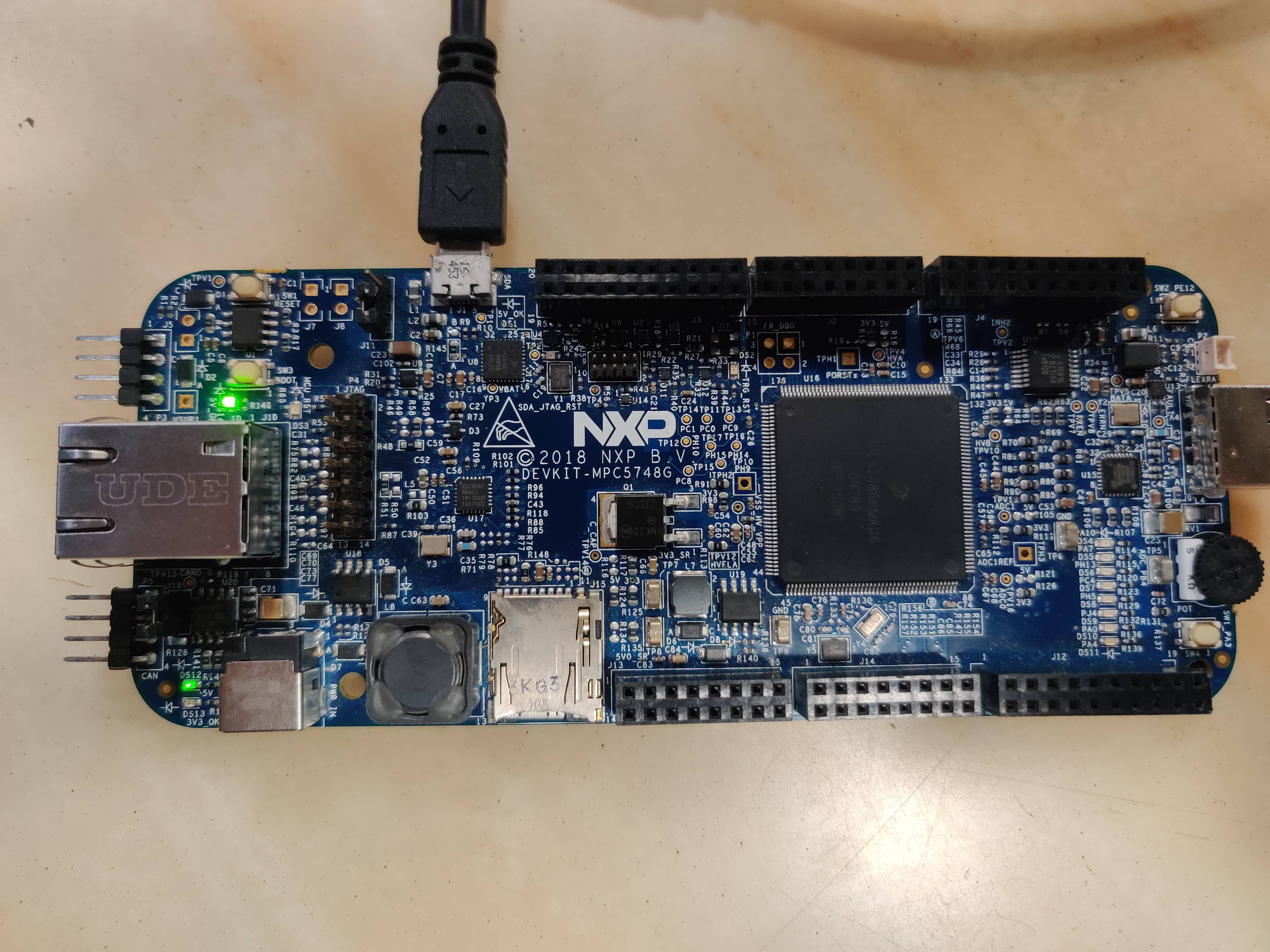
Now if i connect it to PC, I can see the board on COM port, also in the debug configuration it is visible.
The two 5V_OK status LEDs are on all the time(Can be seen in the uploaded image), nothing happens if i press RESET button, Can't see voltages on Header pins(5v or 3.3v).
I have following questions
1. Is the board dead, and cant be used or is there some method by which i can get it working
2. When we connect higher voltage to GPIOs, its the GPIO gets fried or the whole MCU if affected?
3. Is there any protection mechanism available inside the board against such cases.
4. Can the board be repaired?
Thankyou
- Mark as New
- Bookmark
- Subscribe
- Mute
- Subscribe to RSS Feed
- Permalink
- Report Inappropriate Content
Hello,
By mistake I connected one of the GPIO pin(J2-02/PE6) to 12 volt supply.
So you applied overvoltage to the pin. You fried internal regulator most probably.

Now if i connect it to PC, I can see the board on COM port, also in the debug configuration it is visible.
You see response only from driver.
1. Is the board dead, and cant be used or is there some method by which i can get it working
Hard to say, I will not trust such board anymore even if I am able to connect.
2. When we connect higher voltage to GPIOs, its the GPIO gets fried or the whole MCU if affected?
Hard to say, induction can cause a lot of damage inside.
3. Is there any protection mechanism available inside the board against such cases.
There is High voltage detector, but you have applied the voltage directly to IO pin, that is issue.
4. Can the board be repaired?
If you exchange just micro I expect it should be fine. I do not know what else was connected to the pin. If only voltage I do not expect any other board component to be damaged.
Best regards,
Peter
- Mark as New
- Bookmark
- Subscribe
- Mute
- Subscribe to RSS Feed
- Permalink
- Report Inappropriate Content
Thanks peter for your reply,
I did not understand the last part (If you exchange just micro I expect it should be fine), Can you explain a bit more on this,
To pin was set to be a input pin, and i had connected a 10k pullup resister (pin to 3.3v of the board).
Thankyou for pointing this out, I just checked the connection which i have is as below, It was the 3.3V terminal which got shorted to 12V, The switch was open at the time.

Now the situation is different, If the 3.3 volt directly goes to the MCU, then the MCU is getting 12 volt input which is a problem.
The voltages at test points TP7 and TP8 are 0.9V and 2.3V when i start the board and eventually drops to 0 and 1.26 if i keep the boards on for some time.
thanks
- Mark as New
- Bookmark
- Subscribe
- Mute
- Subscribe to RSS Feed
- Permalink
- Report Inappropriate Content
Hello,
If you are generating this 3,3V externally to micro, make sure your regulator outputs 3,3V and its not also fried.
If you replace the micro, first make sure all supply voltages are in specified correct ranges.
As I do not have any view on this issue from HW point, I can only suggest to replace micro on board and check the supply voltages.
Best regards,
Peter