- NXP Forums
- Product Forums
- General Purpose MicrocontrollersGeneral Purpose Microcontrollers
- i.MX Forumsi.MX Forums
- QorIQ Processing PlatformsQorIQ Processing Platforms
- Identification and SecurityIdentification and Security
- Power ManagementPower Management
- MCX Microcontrollers
- S32G
- S32K
- S32V
- MPC5xxx
- Other NXP Products
- Wireless Connectivity
- S12 / MagniV Microcontrollers
- Powertrain and Electrification Analog Drivers
- Sensors
- Vybrid Processors
- Digital Signal Controllers
- 8-bit Microcontrollers
- ColdFire/68K Microcontrollers and Processors
- PowerQUICC Processors
- OSBDM and TBDML
-
- Solution Forums
- Software Forums
- MCUXpresso Software and ToolsMCUXpresso Software and Tools
- CodeWarriorCodeWarrior
- MQX Software SolutionsMQX Software Solutions
- Model-Based Design Toolbox (MBDT)Model-Based Design Toolbox (MBDT)
- FreeMASTER
- eIQ Machine Learning Software
- Embedded Software and Tools Clinic
- S32 SDK
- S32 Design Studio
- Vigiles
- GUI Guider
- Zephyr Project
- Voice Technology
- Application Software Packs
- Secure Provisioning SDK (SPSDK)
- Processor Expert Software
-
- Topics
- Mobile Robotics - Drones and RoversMobile Robotics - Drones and Rovers
- NXP Training ContentNXP Training Content
- University ProgramsUniversity Programs
- Rapid IoT
- NXP Designs
- SafeAssure-Community
- OSS Security & Maintenance
- Using Our Community
-
-
- Home
- :
- MCUXpresso Software and Tools
- :
- MCUXpresso IDE
- :
- PWM module in MKV46F256VLL16
PWM module in MKV46F256VLL16
- Subscribe to RSS Feed
- Mark Topic as New
- Mark Topic as Read
- Float this Topic for Current User
- Bookmark
- Subscribe
- Mute
- Printer Friendly Page
- Mark as New
- Bookmark
- Subscribe
- Mute
- Subscribe to RSS Feed
- Permalink
- Report Inappropriate Content
Hi,
I have gone through the reference modules and the datasheet of the micro MKV46F256VLL16. But I'm not able to understand how VAL1 to VAL5 are set if I'm using inbuilt functions? What if I have to change those values that are present in the built functions?
I have gone through the example code that explains nano edge PWM, but I have a few doubts in them. I am hoping that someone would help me clear it out.
How will I be able to set FRACVAL if I'm using the inbuilt functions? Along with the PWM block, should I be using the SIM, MCG and PMC modules? Instead of 3.2GHz if I want 5GHz, which module should be changed?
In the inbuilt funciton, SIM_PWRC_SRPWRRDY(x); what does x mean? How much value should I be putting to it?
Thanks in advance
Solved! Go to Solution.
- Mark as New
- Bookmark
- Subscribe
- Mute
- Subscribe to RSS Feed
- Permalink
- Report Inappropriate Content
So, from the documents, I understand that there are 5 registers for FRACVALS.
(Refer TRM)
FRACVAL1 is to control the PWM period width
FRACVAL2 controls the PWM_A turn on timing and turn off delay of PWM_B in complementary mode.
FRACVAL3 controls the PWM_A turn off timing and turn on delay of PWM_B in complementary mode.
FRACVAL4 controls the PWM_B turn on timing and turn off delay of PWM_A in complementary mode.
FRACVAL5 controls the PWM_B turn off timing and turn on delay of PWM_A in complementary mode.
These registers get activated only when they are loaded into the PWM pins. To turn on the nano edge, we need to
1. activate the bandgap buffer should be enabled
2. power on the nano edge
3. power on of the nano edge detector
PMC->REGSC |= 0x01; //setting the BGBE bit bandgap buffer enable
PWMA->SM[0].FRCTRL = 0x114; //powering on of the nano edge
SIM->PWRC = 0x100; //NanoEdge PMC POWER Dectect Enabled
PWMA->SM[0].FRACVAL3 = 15 << 11; //determine the fractional value required
PWM_SetPwmLdok(PWMA, kPWM_Control_Module_0, true);//load the value
This does the trick
Thank you @jingpan for the inputs.
- Mark as New
- Bookmark
- Subscribe
- Mute
- Subscribe to RSS Feed
- Permalink
- Report Inappropriate Content
Hello @jingpan, I understand but it is still not clear for me and I have a few questions regarding the same.
1. When you say "use PWM_UpdatePwmDutycycle() to change VAL2~5 directly." which Value will I be changing in VAL2 to VAL5 when I call the example function below?
PWM_UpdatePwmDutycycle(PWMA, kPWM_Module_0, kPWM_PwmA, kPWM_EdgeAligned, 10);
2.For the nano edge function, even if we use the config tools, should we be adding the PLLset function in our code? I have tried to use nanoedge PWM using the config tool. For this, I have used FBE mode of operation. I have activated the nanoedge functionality, yet it shows an error. How will I be able to solve this?
The PLLS is selected to operate in PLL mode. The CLKS is configured to output of PLLS. (if this configuration is changed, then the modes vary.) Because of this, I am not able to generate the code.
Please give out a manual which defines what to use in the different modes of operations as it is not clearly stated in the TRM. Thank you
- Mark as New
- Bookmark
- Subscribe
- Mute
- Subscribe to RSS Feed
- Permalink
- Report Inappropriate Content
Hi,
1. There last parameter of PWM_UpdatePwmDutycycle() pwmVal is the percentage of PWM duty cycle.
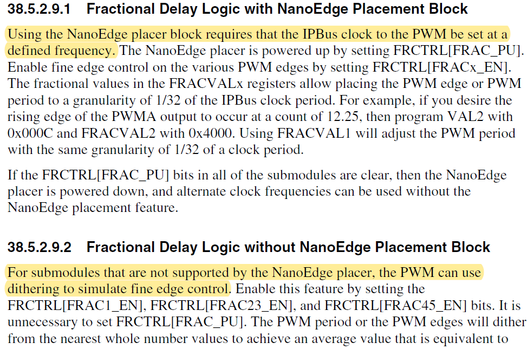
2. FBE is PLL bypassed external mode, it use external clock to Past Peripheral clock directly. But the nanoedge 2x clock must be equal to 2x fast peripheral clock. Please see section 6.5.1 in RM. So, if you want to use nanoedge fucntion, you can't use PBE mode.
Regards,
Jing
- Mark as New
- Bookmark
- Subscribe
- Mute
- Subscribe to RSS Feed
- Permalink
- Report Inappropriate Content
So, from the documents, I understand that there are 5 registers for FRACVALS.
(Refer TRM)
FRACVAL1 is to control the PWM period width
FRACVAL2 controls the PWM_A turn on timing and turn off delay of PWM_B in complementary mode.
FRACVAL3 controls the PWM_A turn off timing and turn on delay of PWM_B in complementary mode.
FRACVAL4 controls the PWM_B turn on timing and turn off delay of PWM_A in complementary mode.
FRACVAL5 controls the PWM_B turn off timing and turn on delay of PWM_A in complementary mode.
These registers get activated only when they are loaded into the PWM pins. To turn on the nano edge, we need to
1. activate the bandgap buffer should be enabled
2. power on the nano edge
3. power on of the nano edge detector
PMC->REGSC |= 0x01; //setting the BGBE bit bandgap buffer enable
PWMA->SM[0].FRCTRL = 0x114; //powering on of the nano edge
SIM->PWRC = 0x100; //NanoEdge PMC POWER Dectect Enabled
PWMA->SM[0].FRACVAL3 = 15 << 11; //determine the fractional value required
PWM_SetPwmLdok(PWMA, kPWM_Control_Module_0, true);//load the value
This does the trick
Thank you @jingpan for the inputs.
- Mark as New
- Bookmark
- Subscribe
- Mute
- Subscribe to RSS Feed
- Permalink
- Report Inappropriate Content
Hi soaring_sun,
1. VAL0/1 control period and VAL2~5 control dutycycle. In the driver, it use PWM_DRV_Init3PhPwm() function to set period and dutycycle. The data is saved in pwmSignal structure. When change dutycycle, it use PWM_UpdatePwmDutycycle() to change VAL2~5 directly.
2.But the driver is not cover nanoedge function. Customer have to add this function code by themselves.
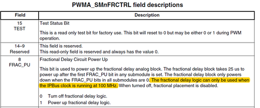
3. You can only get 3.2G. Because the fractional delay logic can only be used when the IPBus clock is running at 100 MHz.
4. x is the bit value you want to write into this register, it's 0 or 1.
Regards,
Jing


