
- Forums
- Product Forums
- General Purpose MicrocontrollersGeneral Purpose Microcontrollers
- i.MX Forumsi.MX Forums
- QorIQ Processing PlatformsQorIQ Processing Platforms
- Identification and SecurityIdentification and Security
- Power ManagementPower Management
- Wireless ConnectivityWireless Connectivity
- RFID / NFCRFID / NFC
- Advanced AnalogAdvanced Analog
- Neural Processing UnitsNeural Processing Units
- MCX Microcontrollers
- S32G
- S32K
- S32V
- MPC5xxx
- Other NXP Products
- S12 / MagniV Microcontrollers
- Powertrain and Electrification Analog Drivers
- Sensors
- Vybrid Processors
- Digital Signal Controllers
- 8-bit Microcontrollers
- ColdFire/68K Microcontrollers and Processors
- PowerQUICC Processors
- OSBDM and TBDML
- S32M
- S32Z/E
-
- Solution Forums
- Software Forums
- MCUXpresso Software and ToolsMCUXpresso Software and Tools
- CodeWarriorCodeWarrior
- MQX Software SolutionsMQX Software Solutions
- Model-Based Design Toolbox (MBDT)Model-Based Design Toolbox (MBDT)
- FreeMASTER
- eIQ Machine Learning Software
- Embedded Software and Tools Clinic
- S32 SDK
- S32 Design Studio
- GUI Guider
- Zephyr Project
- Voice Technology
- Application Software Packs
- Secure Provisioning SDK (SPSDK)
- Processor Expert Software
- Generative AI & LLMs
-
- Topics
- Mobile Robotics - Drones and RoversMobile Robotics - Drones and Rovers
- NXP Training ContentNXP Training Content
- University ProgramsUniversity Programs
- Rapid IoT
- NXP Designs
- SafeAssure-Community
- OSS Security & Maintenance
- Using Our Community
-
- Cloud Lab Forums
-
- Knowledge Bases
- ARM Microcontrollers
- i.MX Processors
- Identification and Security
- Model-Based Design Toolbox (MBDT)
- QorIQ Processing Platforms
- S32 Automotive Processing Platform
- Wireless Connectivity
- CodeWarrior
- MCUXpresso Suite of Software and Tools
- MQX Software Solutions
- RFID / NFC
- Advanced Analog
- Neural Processing Units
-
- NXP Tech Blogs
- Home
- :
- General Purpose Microcontrollers
- :
- Kinetis Microcontrollers
- :
- UART Problem on the RX line
UART Problem on the RX line
- Subscribe to RSS Feed
- Mark Topic as New
- Mark Topic as Read
- Float this Topic for Current User
- Bookmark
- Subscribe
- Mute
- Printer Friendly Page
- Mark as New
- Bookmark
- Subscribe
- Mute
- Subscribe to RSS Feed
- Permalink
- Report Inappropriate Content
Hello everybody
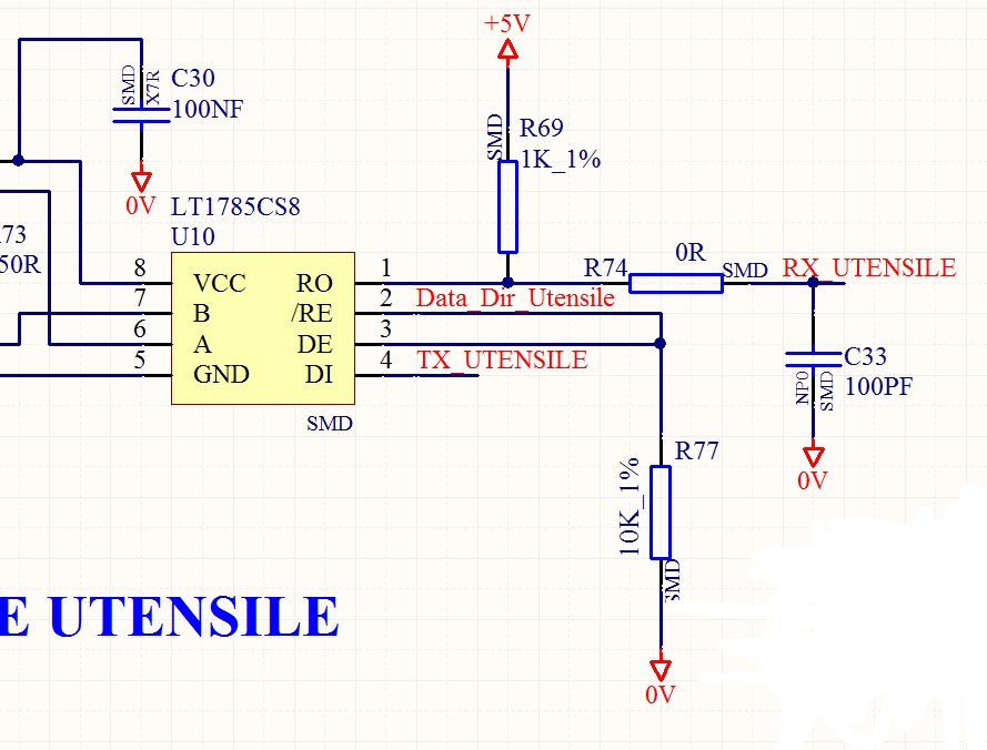
I'm dealing with a problem that make me crazy. In my project I communicate with a board via RS485 interface, and I use UART0 of the MKE04Z128VLH4 mcu and a transceiver like LT1785. I use half duplex communication: I use a line to toggle data direction, and the UART0 to send/receive data to/from extern board. It states that it is a solution that I use for years by other MCU, and I've never had problems. So, MCUs is a "master", sends data and wait the reply from extern board, and to do it, use a pin, configured as outtup: when MCU have to transmit it put the pin (let me call it DATA_DIR) high, sends data, and turn DATA_DIR low, then it waits for data from the extern board. The problem is that toggling DATA_DIR causes toggling of RX pin, and it causes falses RX interrupts, and uncorrect data. I can't understand why with others MCUs the problem there was not. For example on the board that have to communicate with this one, I use the same scheme, and MKE02Z32VLC2, and it works fine!!!.
I've attached imagine of the schemes used to communicate: as you can see there's a pullup of 1K on RX pin. Usually communication is like in the RX.jpg file: line RX is attached to 5V, and when data comes, it switches. With UART0 of MKE04Z128VLH4 RX line is always low, and it switches when data arrives, but HW and SW are the same as for MKE02Z32VLC2 solution.
Where I'm doing worng? I can't understand why or maybe I didn't read a note on UART0 that is different from others.
I hope someone can help me to understand where's the matter.
Thank you very much
Roberto
Here I post UART0 configuration an DATA_DIR setting
//------ Seriale numero 1 --> 57600, 8 bit, nessun controllo HW
UART0_BDH = UART0_VALUE_BDH; //Formula --> BusClock/(16 * BD) = velocità
UART0_BDL = UART0_VALUE_BDL; //Quindi per avere 57600 BD = BusClock/(16*57600) = 26
UART0_C1 = 0x00;
UART0_C2 |= UART_C2_RIE_MASK; //interrupt enable on RX
SET_UART0_C2_TE; //TX On
SET_UART0_C2_RE; //RX On
GPIOB_PDDR |= PTF3_MASK; //Port PFT3 used as an output for data direction
GPIOB_PCOR |= PTF3_MASK //Port PFT3 goes low, so i'm in RX mode
Solved! Go to Solution.
- Mark as New
- Bookmark
- Subscribe
- Mute
- Subscribe to RSS Feed
- Permalink
- Report Inappropriate Content
When I finished to write my question I found the answer: Problem was not SW but HW configuration of A/B pins on the transceiver. In this way A<B -> RX low when we're in a steady state, and so when we change the line RO goes in Hiz that means RX line goes high. Changing pullup/pulldown sequence on A/B pins solve the problem.
I hope this can be helpful. Thank you very much
Roberto