
- Forums
- Product Forums
- General Purpose MicrocontrollersGeneral Purpose Microcontrollers
- i.MX Forumsi.MX Forums
- QorIQ Processing PlatformsQorIQ Processing Platforms
- Identification and SecurityIdentification and Security
- Power ManagementPower Management
- Wireless ConnectivityWireless Connectivity
- RFID / NFCRFID / NFC
- Advanced AnalogAdvanced Analog
- Neural Processing UnitsNeural Processing Units
- MCX Microcontrollers
- S32G
- S32K
- S32V
- MPC5xxx
- Other NXP Products
- S12 / MagniV Microcontrollers
- Powertrain and Electrification Analog Drivers
- Sensors
- Vybrid Processors
- Digital Signal Controllers
- 8-bit Microcontrollers
- ColdFire/68K Microcontrollers and Processors
- PowerQUICC Processors
- OSBDM and TBDML
- S32M
- S32Z/E
-
- Solution Forums
- Software Forums
- MCUXpresso Software and ToolsMCUXpresso Software and Tools
- CodeWarriorCodeWarrior
- MQX Software SolutionsMQX Software Solutions
- Model-Based Design Toolbox (MBDT)Model-Based Design Toolbox (MBDT)
- FreeMASTER
- eIQ Machine Learning Software
- Embedded Software and Tools Clinic
- S32 SDK
- S32 Design Studio
- GUI Guider
- Zephyr Project
- Voice Technology
- Application Software Packs
- Secure Provisioning SDK (SPSDK)
- Processor Expert Software
- Generative AI & LLMs
-
- Topics
- Mobile Robotics - Drones and RoversMobile Robotics - Drones and Rovers
- NXP Training ContentNXP Training Content
- University ProgramsUniversity Programs
- Rapid IoT
- NXP Designs
- SafeAssure-Community
- OSS Security & Maintenance
- Using Our Community
-
- Cloud Lab Forums
-
- Knowledge Bases
- ARM Microcontrollers
- i.MX Processors
- Identification and Security
- Model-Based Design Toolbox (MBDT)
- QorIQ Processing Platforms
- S32 Automotive Processing Platform
- Wireless Connectivity
- CodeWarrior
- MCUXpresso Suite of Software and Tools
- MQX Software Solutions
- RFID / NFC
- Advanced Analog
- Neural Processing Units
-
- NXP Tech Blogs
- Home
- :
- 汎用マイクロコントローラ
- :
- Kinetisマイクロコントローラ
- :
- TWR-K60F120M PLL Not Lock
TWR-K60F120M PLL Not Lock
- RSS フィードを購読する
- トピックを新着としてマーク
- トピックを既読としてマーク
- このトピックを現在のユーザーにフロートします
- ブックマーク
- 購読
- ミュート
- 印刷用ページ
- 新着としてマーク
- ブックマーク
- 購読
- ミュート
- RSS フィードを購読する
- ハイライト
- 印刷
- 不適切なコンテンツを報告
Hello,
we have been able to create and blink light on TWR-K60F120M using internal clock feeding the FLL.
Now, we try to configure the OSC external ref clock (50 MHz from board) to feed the PLL and so on.
The code generation went fine and download OK, but it got stuck waiting for PLL locked at line 486 of Cpu.c file.
we use KDS 3.0 and KSDK 1.3.
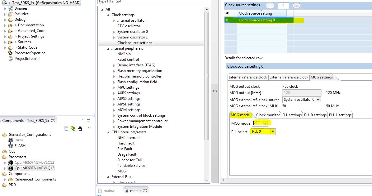
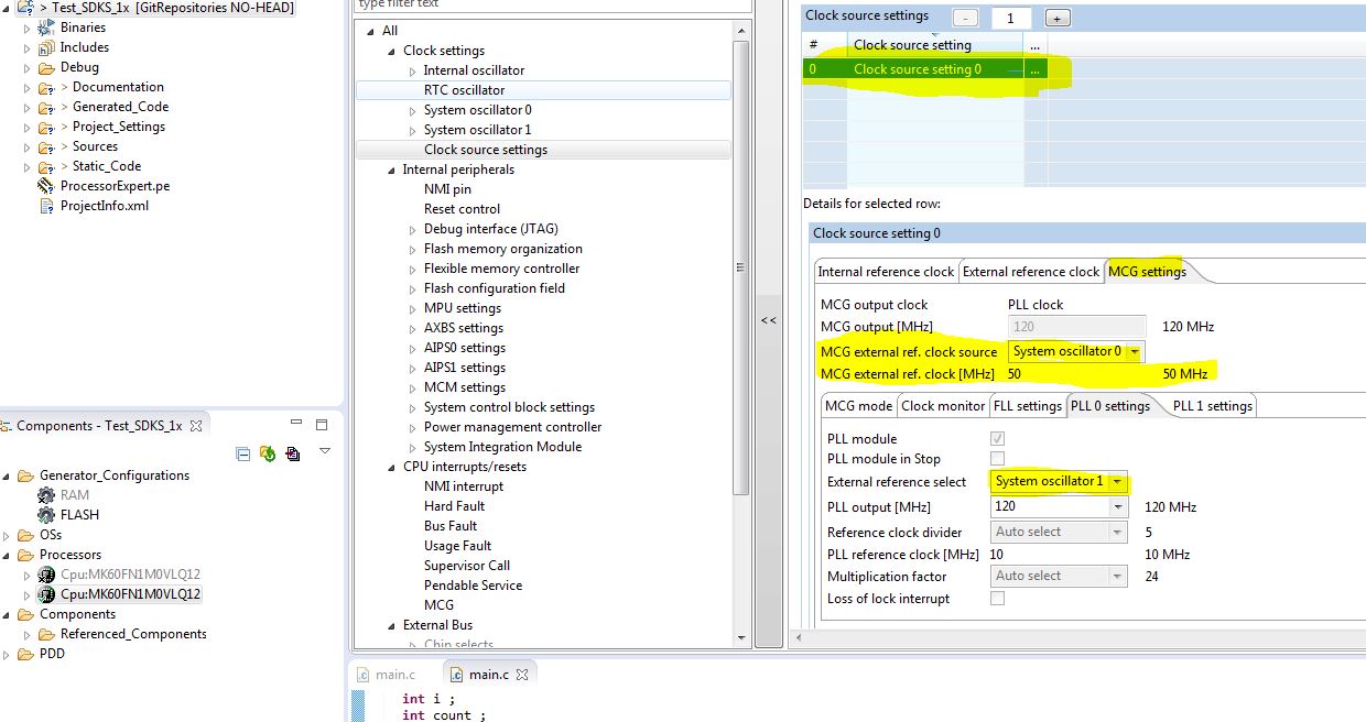
Attached is the snap shot of the clock configuration and the generated clock configuration codes.
Our intention is to drive 50 MHz clock from the TWR board to the EXTAL1 input (system oscillator 1) and then use this clock to drive PLL. PLL output is 120 MHz. The 50 MHz External clock is divided by 10 prior to feed the PLL,
On TWR board, i have J18 ON to drive power to OSC and J6 off which means the 50 MHz osc clock is enable according to the schematic and the user jumper guide.
Can you please give us any comment on this?
Thank you,
Henry
Original Attachment has been moved to: Cpu.c.zip
解決済! 解決策の投稿を見る。
- 新着としてマーク
- ブックマーク
- 購読
- ミュート
- RSS フィードを購読する
- ハイライト
- 印刷
- 不適切なコンテンツを報告
Hi Henry,
I think the "MCG external ref. clock source" mean "MCG FLL external reference clock".


Since you want to use 50MHz external reference clock drive PLL output 120 MHz . The "External reference select" in PLL 0 settings should be "System oscillator 0".

About the "Problem with K60 Silicon (Mask Set 0N96B)", you can use the method in USB with the TWR-K60F120M and TWR-K70F120M.
Best Regards,
Robin
-----------------------------------------------------------------------------------------------------------------------
Note: If this post answers your question, please click the Correct Answer button. Thank you!
-----------------------------------------------------------------------------------------------------------------------
- 新着としてマーク
- ブックマーク
- 購読
- ミュート
- RSS フィードを購読する
- ハイライト
- 印刷
- 不適切なコンテンツを報告
Hi
To use the external 50MHz oscillator (on EXTAL - PTA18) to generate 120MHz the code below can be used.
Note that the silicon errata is not an issue for external oscillator (only for the 12MHz crystal source) and I believe Eric had made a mistake stating that the crystal source is the only option when using USB because it is not a problem to use USB from the 50MHz oscillator when the core speed is set to 120MHz (code also below).
Note that I also plugged in the actual [hex values] used as reference in case the defines are not clear.
See http://www.utasker.com/kinetis/TWR-K60F120M.html for full code (including full K60F120 project framework with Ethernet, USB, FAT etc.).
Relying on PE to generate setups can be risky (and time consuming if one makes an input mistake of needs to solve bugs) so it is often best to do it properly (it is quite simple - see also http://www.utasker.com/kinetis/MCG.html).
Simulation further below also confirms (and avoids any debugging effort).
Regards
Mark
// CPU clocks
//
MCG_C2 = (MCG_C2_RANGE_8M_32M | MCG_C2_LOCRE0); // [0xa0] select external clock source (with reset on clock loss)
MCG_C1 = (MCG_C1_CLKS_EXTERN_CLK | MCG_C1_FRDIV_1024); // [0xa8] switch to external input clock (the FLL input clock is set to as close to its input range as possible, although this is not absolutely necessary since the FLL will not be used)
while ((MCG_S & MCG_S_IREFST) != 0) {} // loop until the FLL source is no longer the internal reference clock
while ((MCG_S & MCG_S_CLKST_MASK) != MCG_S_CLKST_EXTERN_CLK) {} // loop until the external reference clock source is valid
MCG_C5 = ((CLOCK_DIV - 1) | MCG_C5_PLLSTEN0); // [0x24] now move from state FEE to state PBE (or FBE) PLL remains enabled in normal stop modes
MCG_C6 = ((CLOCK_MUL - MCG_C6_VDIV0_LOWEST) | MCG_C6_PLLS); // [0x48] set the PLL multiplication factor
while ((MCG_S & MCG_S_PLLST) == 0) {} // loop until the PLLS clock source becomes valid
while ((MCG_S & MCG_S_LOCK) == 0) {} // loop until PLL locks
SIM_CLKDIV1 = (((SYSTEM_CLOCK_DIVIDE - 1) << 28) | ((BUS_CLOCK_DIVIDE - 1) << 24) | ((FLEX_CLOCK_DIVIDE - 1) << 20) | ((FLASH_CLOCK_DIVIDE - 1) << 16)); // [0x0124000] prepare bus clock divides
MCG_C1 = (MCG_C1_CLKS_PLL_FLL | MCG_C1_FRDIV_1024); // [0x28] finally move from PBE to PEE mode - switch to PLL clock
while ((MCG_S & MCG_S_CLKST_MASK) != MCG_S_CLKST_PLL) {} // loop until the PLL clock is selected
// USB clock
//
SIM_SOPT2 |= (SIM_SOPT2_USBSRC | SIM_SOPT2_PLLFLLSEL | SIM_SOPT2_USBFSRC_MCGPLL0); // [0x44451000] set the source to MCGPLL0CLK
SIM_CLKDIV2 |= (((((USB_CLOCK_SOURCE * 2)/48000000) - 1) << 1) | SIM_CLKDIV2_USBFRAC); // [0x00000009] the value of the clock source must be chosen to allow 48MHz to be achieved!

- 新着としてマーク
- ブックマーク
- 購読
- ミュート
- RSS フィードを購読する
- ハイライト
- 印刷
- 不適切なコンテンツを報告
Hi Mark,
Thank you so much for your help.
Henry
- 新着としてマーク
- ブックマーク
- 購読
- ミュート
- RSS フィードを購読する
- ハイライト
- 印刷
- 不適切なコンテンツを報告
Hi Henry,
It seems that you have selected the wrong External Reference.

Best Regards,
Robin
-----------------------------------------------------------------------------------------------------------------------
Note: If this post answers your question, please click the Correct Answer button. Thank you!
-----------------------------------------------------------------------------------------------------------------------
- 新着としてマーク
- ブックマーク
- 購読
- ミュート
- RSS フィードを購読する
- ハイライト
- 印刷
- 不適切なコンテンツを報告
Hi Robin,
Thank you for your help.
MCG External Reference Clock selection only gave user two options: System Oscillator 0 and RTC clock. Not sure why. Now, i wonder what MCG External reference clock means?
However, searching around the web, i came to know that there is an issue with K60F120 silicon as highlighted by Erich Styger in the link below:
https://mcuoneclipse.com/2013/10/27/usb-with-the-twr-k60f120m-and-twr-k70f120m/
I followed his recommendation and make it passed through the PLL locking while loop.
One note is that the processor expert generates this codes:
/* MCG_C10: LOCRE2=0,??=0,RANGE1=2,HGO1=0,EREFS1=0,??=0,??=0 */
MCG_C10 = MCG_C10_RANGE1(0x02);
/* MCG_C2: LOCRE0=0,??=0,RANGE0=2,HGO0=0,EREFS0=0,LP=0,IRCS=0 */
MCG_C2 = MCG_C2_RANGE0(0x02);
and i have to change to this codes to make it pass the PLL locking step.
/* MCG_C10: LOCRE2=0,??=0,RANGE1=2,HGO1=0,EREFS1=0,??=0,??=0 */
MCG_C10 = (MCG_C10_RANGE1(0x01) | MCG_C10_EREFS1_MASK);
/* MCG_C2: LOCRE0=0,??=0,RANGE0=2,HGO0=0,EREFS0=0,LP=0,IRCS=0 */
MCG_C2 = MCG_C2_RANGE0(0x01);
Note that the " | MCG_C10_EREFS1_MASK" is not generated by processor expert, but that bit-wise "or" is needed otherwise it won't make it through the PLL locking. i need to read user programming reference further to understand this Mask bit a bit more.
i will try to check the PLL output clock correctly generated at 120 Mhz tomorrow by trying to output the clock to one of the pin and observe it on the scope. For now, i can make it through the PLL lock to continue on my evaluation which is good. According to the link above, It seems that the issue does not exist on TWR-K70F120M.
i don't know why, but it seems to be a coincidence that the KDSK does "not" support TWR-K60F120M board but supports TWR-K70F120M board. Maybe Freescale does not want user to continue with TWR-K60F120M anymore? just a wild guess from my part.
cheer,
Henry
- 新着としてマーク
- ブックマーク
- 購読
- ミュート
- RSS フィードを購読する
- ハイライト
- 印刷
- 不適切なコンテンツを報告
Hi Henry,
I think the "MCG external ref. clock source" mean "MCG FLL external reference clock".
Since you want to use 50MHz external reference clock drive PLL output 120 MHz . The "External reference select" in PLL 0 settings should be "System oscillator 0".
About the "Problem with K60 Silicon (Mask Set 0N96B)", you can use the method in USB with the TWR-K60F120M and TWR-K70F120M.
Best Regards,
Robin
-----------------------------------------------------------------------------------------------------------------------
Note: If this post answers your question, please click the Correct Answer button. Thank you!
-----------------------------------------------------------------------------------------------------------------------
- 新着としてマーク
- ブックマーク
- 購読
- ミュート
- RSS フィードを購読する
- ハイライト
- 印刷
- 不適切なコンテンツを報告
Hi Robin,
Thank you for your help again. I think i made a mistake when looking at the schematic on clock routing.
you are right. the External 50 MHz does not have any restriction. I tested that and it works well.
Thanks,
Henry