
- Forums
- Product Forums
- General Purpose MicrocontrollersGeneral Purpose Microcontrollers
- i.MX Forumsi.MX Forums
- QorIQ Processing PlatformsQorIQ Processing Platforms
- Identification and SecurityIdentification and Security
- Power ManagementPower Management
- Wireless ConnectivityWireless Connectivity
- RFID / NFCRFID / NFC
- Advanced AnalogAdvanced Analog
- Neural Processing UnitsNeural Processing Units
- MCX Microcontrollers
- S32G
- S32K
- S32V
- MPC5xxx
- Other NXP Products
- S12 / MagniV Microcontrollers
- Powertrain and Electrification Analog Drivers
- Sensors
- Vybrid Processors
- Digital Signal Controllers
- 8-bit Microcontrollers
- ColdFire/68K Microcontrollers and Processors
- PowerQUICC Processors
- OSBDM and TBDML
- S32M
- S32Z/E
-
- Solution Forums
- Software Forums
- MCUXpresso Software and ToolsMCUXpresso Software and Tools
- CodeWarriorCodeWarrior
- MQX Software SolutionsMQX Software Solutions
- Model-Based Design Toolbox (MBDT)Model-Based Design Toolbox (MBDT)
- FreeMASTER
- eIQ Machine Learning Software
- Embedded Software and Tools Clinic
- S32 SDK
- S32 Design Studio
- GUI Guider
- Zephyr Project
- Voice Technology
- Application Software Packs
- Secure Provisioning SDK (SPSDK)
- Processor Expert Software
- Generative AI & LLMs
-
- Topics
- Mobile Robotics - Drones and RoversMobile Robotics - Drones and Rovers
- NXP Training ContentNXP Training Content
- University ProgramsUniversity Programs
- Rapid IoT
- NXP Designs
- SafeAssure-Community
- OSS Security & Maintenance
- Using Our Community
-
- Cloud Lab Forums
-
- Knowledge Bases
- ARM Microcontrollers
- i.MX Processors
- Identification and Security
- Model-Based Design Toolbox (MBDT)
- QorIQ Processing Platforms
- S32 Automotive Processing Platform
- Wireless Connectivity
- CodeWarrior
- MCUXpresso Suite of Software and Tools
- MQX Software Solutions
- RFID / NFC
- Advanced Analog
- Neural Processing Units
-
- NXP Tech Blogs
- Home
- :
- General Purpose Microcontrollers
- :
- Kinetis Microcontrollers
- :
- Re: Programming the MK22FN1M0AVMC12
Programming the MK22FN1M0AVMC12
- Subscribe to RSS Feed
- Mark Topic as New
- Mark Topic as Read
- Float this Topic for Current User
- Bookmark
- Subscribe
- Mute
- Printer Friendly Page
- Mark as New
- Bookmark
- Subscribe
- Mute
- Subscribe to RSS Feed
- Permalink
- Report Inappropriate Content
Hello,
I have previously been working with a custom board with a Kinetis MK20 (MK20DX256VLH7) without problems.
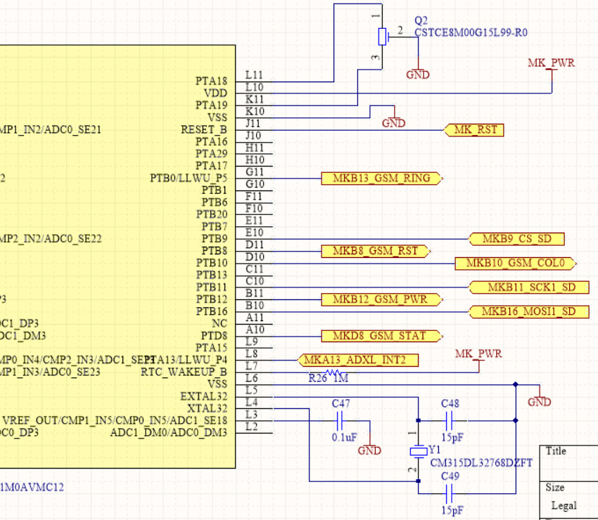
Now I have designed a new board for the MK22FN1M0AVMC12 following the schematic from the Tower Kit TWR-K21F120M.
I am currently trying to program the uC using Kinetis Design Studio and the PE Micro Multilink Universal through SWD, (which worked fine in my previous design) without success, and I am getting the error: "GDB server was not able to establish a connection to the target processor", attached a screenshot of the errors I get.
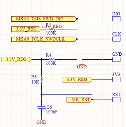
Attached I also include the main conections of the uC in the design, as well as the SWD interface. At first I thought that the problem was that I had a pullup resistor in SWD_CLK, and I read somewhere it shouldnt have this resistor, so I removed it, but still couldnt connect to the uC.
I have tried building a project from scratch and using the SDK for this uC downloaded from the SDK builder at mcuxpresso.nxp.com, attempting to load an empty project without success.
Could you give me hints on where should I look for possible errors? The 3.3V of the board seems correct, and the PE micro also receives this power. Should I make any modifications to the programming in KDS, or should some hardware items be modified to try again?
Thank you in advance for your attention.
Solved! Go to Solution.
- Mark as New
- Bookmark
- Subscribe
- Mute
- Subscribe to RSS Feed
- Permalink
- Report Inappropriate Content
Hi,
VBAT is not likely to be the problem. TWR-K22 connects MCU_PWR with VBAT.
RTC_wakeup_b pin is a open drain output ping. It should be no influence to system.
Vref_OUT is contorled by VREFV1 register. If it is not set, output should be zero.
I think EZP_CS/NMI should be pullup. Because the default value of FPOT is 0xff. It selects the EZP_CS function of the pin. If it is low during power on, device will enter EZPort mode. Then SWD will not work.
Regards
Jing
- Mark as New
- Bookmark
- Subscribe
- Mute
- Subscribe to RSS Feed
- Permalink
- Report Inappropriate Content
Hi Jing,
Thanks for your help! After connecting NMI pin to pullup (I actually needed to disconnect it from a peripheral that was pulling it low) I was able to use SWD for programming.
Thanks for your help!!
- Mark as New
- Bookmark
- Subscribe
- Mute
- Subscribe to RSS Feed
- Permalink
- Report Inappropriate Content
Hi,
It is ok to add a 100K pullup resistor to SWDCLK and SWDIO. In fact, it is recommanded to add a pull resistor. I couldn't find any hardware problem in your attachment. So try to check your power on sequence and connection. Please find KQRUG.pdf on nxp website. It may give you some guidence.
Regards
Jing
- Mark as New
- Bookmark
- Subscribe
- Mute
- Subscribe to RSS Feed
- Permalink
- Report Inappropriate Content
Hi Jing,
Thank you again for your reply!
I have verified connection and still dont find the issue, Power is correct and although I havent used a scope, I can see that the SWD and CLK are changing when attempting programming, but since the setup has been the same than with my previous board (and this previous one is working). I am suspecting something in the design of my board. I have listed some potential problems and measurement results below, could you let me know if this could be the cause?
- VBAT is connected to 3.3V (Same VDD supply of the uC), but datasheet recommends to leave it floating. (I hope this is not the cause because it would be impossible to disconnect it, since it is using a via below the BGA to the power plane)
- RTC_Wakeup_b is connected to the same VDD through a high resistor of 1MOhm, but I will not use this pin for the low power modes in my application
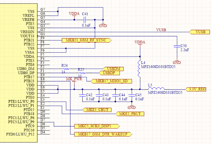
- VREF_Out outputs 0V. Is this normal condition?
- When I connect the USB I see 3.3V in the pin VOUT33, which would suggest the uC is ok, am I right?
Thanks again!
Best Regards,
Ivan
- Mark as New
- Bookmark
- Subscribe
- Mute
- Subscribe to RSS Feed
- Permalink
- Report Inappropriate Content
Addition:
I am also not pulling HIGH the NMI (PTA4), it is connected to an interrupt of a peripheral. Could this be the cause? Attempting this pullup connection would not be straightforward in my board, but if this is likely to solve the problem I can try a couple of things for this pullup.
Could this be the reason?
Thanks!
- Mark as New
- Bookmark
- Subscribe
- Mute
- Subscribe to RSS Feed
- Permalink
- Report Inappropriate Content
Hi,
It seems that the connection between KDS and debug adaptor(MK20) has established. But debug adaptor doesn't find MK22. So please check:
1. If the MK22 is power on correctly
2. If the RESET pin is in correct status
3. If SWD signal is connect to PTA0 and PTA3. If you have a oscilloscope, you can check if there is correct signal on the SWD bus. If you have a JLINK. You also can use JLINK to check if MK22 is in correct status.
4. You can also try most update openSDA bootloader and fimware.
Regards
Jing
- Mark as New
- Bookmark
- Subscribe
- Mute
- Subscribe to RSS Feed
- Permalink
- Report Inappropriate Content
Hi Jing Pan,
Thank you for your reply!
Regarding your suggestions:
1. I have verified that the power is correct at 3.3V, and this is also providing the power for the PE Micro Multilink Universal
2. Reset pin is pulled up to 3.3V by default, but I cannot see the programming sequence as I dont have an oscilloscope
3. Up to where I can check (The uC is BGA), SWD signals are connected to PTA0 and PTA3. I dont have a JLINK, but a PE Micro programmer.
4. I will try the openSDA, but seems unlikely to make a difference, since with the KDS environment I was able to connect to my previous version of the board that had the MK20.
Did you have a chance to look at my design? Are all connections ok or is there something from the hardware point of view that I should try as well? Should I leave SWD_CLK without any pullup or pulldown and keep the pullups in RESET and SWD_DIO?
Thank you again for your attention!
Best,
Ivan