
- Forums
- Product Forums
- General Purpose MicrocontrollersGeneral Purpose Microcontrollers
- i.MX Forumsi.MX Forums
- QorIQ Processing PlatformsQorIQ Processing Platforms
- Identification and SecurityIdentification and Security
- Power ManagementPower Management
- Wireless ConnectivityWireless Connectivity
- RFID / NFCRFID / NFC
- Advanced AnalogAdvanced Analog
- Neural Processing UnitsNeural Processing Units
- MCX Microcontrollers
- S32G
- S32K
- S32V
- MPC5xxx
- Other NXP Products
- S12 / MagniV Microcontrollers
- Powertrain and Electrification Analog Drivers
- Sensors
- Vybrid Processors
- Digital Signal Controllers
- 8-bit Microcontrollers
- ColdFire/68K Microcontrollers and Processors
- PowerQUICC Processors
- OSBDM and TBDML
- S32M
- S32Z/E
-
- Solution Forums
- Software Forums
- MCUXpresso Software and ToolsMCUXpresso Software and Tools
- CodeWarriorCodeWarrior
- MQX Software SolutionsMQX Software Solutions
- Model-Based Design Toolbox (MBDT)Model-Based Design Toolbox (MBDT)
- FreeMASTER
- eIQ Machine Learning Software
- Embedded Software and Tools Clinic
- S32 SDK
- S32 Design Studio
- GUI Guider
- Zephyr Project
- Voice Technology
- Application Software Packs
- Secure Provisioning SDK (SPSDK)
- Processor Expert Software
- Generative AI & LLMs
-
- Topics
- Mobile Robotics - Drones and RoversMobile Robotics - Drones and Rovers
- NXP Training ContentNXP Training Content
- University ProgramsUniversity Programs
- Rapid IoT
- NXP Designs
- SafeAssure-Community
- OSS Security & Maintenance
- Using Our Community
-
- Cloud Lab Forums
-
- Knowledge Bases
- ARM Microcontrollers
- i.MX Processors
- Identification and Security
- Model-Based Design Toolbox (MBDT)
- QorIQ Processing Platforms
- S32 Automotive Processing Platform
- Wireless Connectivity
- CodeWarrior
- MCUXpresso Suite of Software and Tools
- MQX Software Solutions
- RFID / NFC
- Advanced Analog
- Neural Processing Units
-
- NXP Tech Blogs
- Home
- :
- General Purpose Microcontrollers
- :
- Kinetis Microcontrollers
- :
- Low Power modes and internal revulator MK22
Low Power modes and internal revulator MK22
- Subscribe to RSS Feed
- Mark Topic as New
- Mark Topic as Read
- Float this Topic for Current User
- Bookmark
- Subscribe
- Mute
- Printer Friendly Page
Low Power modes and internal revulator MK22
- Mark as New
- Bookmark
- Subscribe
- Mute
- Subscribe to RSS Feed
- Permalink
- Report Inappropriate Content
Hello,
I am working with the microcontroller MK22FN1M0AVMC12 and was reading about entering the low power modes and waking up from them.
I have provided two buttons connected to pins with LLUW functionality, so I can both go into low power modes using a combination of the pressed buttons, or a long-press of one of them, and also allow the wakeup using one of them as a LLUW interrupt.
My first question is if my approach is correct in this matter: Can I use only one button connected to a LLUW pin in order to both go in to sleep mode and wake up from it? This would function as the 'on_off' button of a device, when off means one of the deep sleep modes. Am I correct by doing this?
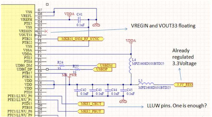
The second question I have is related to the 'internal regulator' mentioned in the different power modes. In my design I am not using the pins 'vregin' and 'vout33', mainly because I am already regulating a battery with an external regulator that also supplies other peripherals which need a higher current than the one provided by vout33. In this sense, I leave 'vregin' and 'vout33' floating, and use my regulated voltage as the input to the VDD pins. With this approach, am I affecting the functionality of the low-power modes since it controls the 'internal regulator'? or is the internal regulator a different one than the one used for vout33, and that is inside the uc after the VDD, in which case the approach of not using vout33 will still allow for the low power modes to work properly.
Besides this, is there any reason I should use the vout33 even if I already have a 3.3v regulated source?
Thank you in advance.
- Mark as New
- Bookmark
- Subscribe
- Mute
- Subscribe to RSS Feed
- Permalink
- Report Inappropriate Content
Hi Pulsatrix P1,
1) You are correct, you can use the same pin to go into sleep mode and wake up from it. When the device is awake, the pin acts as a normal GPIO but in low power it acts as a LLWU pin.
For more information on how to use low-power modes, see Power Management for Kinetis
MCUs application note.
2) The internal regulator is enabled by default when power is applied to VREGIN. If USB is not used in your application, it is recommended to leave VREGIN and VOUT33 pins remain floating. This will not affect the functionality of the low-power modes. When the regulator is enabled, it can be configured to go to STANDBY mode in some low-power modes.
I see in the attached schematic that you are using the USB0_DP and USB0_DM signals, so if you are using USB in your application you need to connect VREGIN because the USB module powers from the internal regulator only.
Please take a look at section 3.9.1 Universal Serial Bus (USB) FS Subsystem in the reference manual for some example configurations. Also, the Kinetis Peripheral Module Quick Reference User Guide has more information about the USB module on the Kinetis family of MCUs.
Best regards,
Gerardo
- Mark as New
- Bookmark
- Subscribe
- Mute
- Subscribe to RSS Feed
- Permalink
- Report Inappropriate Content
Hi Gerardo,
Thank you very much for your useful reply. My question 1 is fully solved.
Regarding my question 2, I indeed intend to use (in the future) the USB connection. Following your advice, then I will continue to power the VDD from the microcontroller from my external 3.3V regulator in the board, but at the same time will supply the pin VREGIN, so I can use the USB when needed (Am I correct?) If this is the case, should I just connect this VREGIN to the same 3.3V (already regulated) that I use for VDD, or should I directly use a 3.7V battery that is also available in the board? Is there any reason to choose for one or the other?
In addition, as I will not need the output of this regulator and will connect it only for USB purposes, then I will leave its output floating.
Thank you in advance.
Best Regards,
Ivan
- Mark as New
- Bookmark
- Subscribe
- Mute
- Subscribe to RSS Feed
- Permalink
- Report Inappropriate Content
Hi Ivan,
According to the datasheet, VREGIN voltage can be from 2.7V - 5.5V. When the input power supply is below 3.6 V, the regulator goes to pass-through mode. So in your case, you can use either, if you use your 3.3V regulated supply, the USB voltage regulator will be in pass-through mode and if you use the 3.7V from your battery the LDO linear regulator will be active. Also add a capacitor to the VOUT33 pin as shown in the following figure from the reference manual:

Regards,
Gerardo
- Mark as New
- Bookmark
- Subscribe
- Mute
- Subscribe to RSS Feed
- Permalink
- Report Inappropriate Content
Thank you!. I have done this, and have actually chosen to connect VREGIN to VUSB, so that it is only powered when USB is connected, as it is suggested in the datasheet, page 132.
Best Regards,
Ivan
- Mark as New
- Bookmark
- Subscribe
- Mute
- Subscribe to RSS Feed
- Permalink
- Report Inappropriate Content
Edit: Page 133 better describes this case.