
- Forums
- Product Forums
- General Purpose MicrocontrollersGeneral Purpose Microcontrollers
- i.MX Forumsi.MX Forums
- QorIQ Processing PlatformsQorIQ Processing Platforms
- Identification and SecurityIdentification and Security
- Power ManagementPower Management
- Wireless ConnectivityWireless Connectivity
- RFID / NFCRFID / NFC
- Advanced AnalogAdvanced Analog
- Neural Processing UnitsNeural Processing Units
- MCX Microcontrollers
- S32G
- S32K
- S32V
- MPC5xxx
- Other NXP Products
- S12 / MagniV Microcontrollers
- Powertrain and Electrification Analog Drivers
- Sensors
- Vybrid Processors
- Digital Signal Controllers
- 8-bit Microcontrollers
- ColdFire/68K Microcontrollers and Processors
- PowerQUICC Processors
- OSBDM and TBDML
- S32M
- S32Z/E
-
- Solution Forums
- Software Forums
- MCUXpresso Software and ToolsMCUXpresso Software and Tools
- CodeWarriorCodeWarrior
- MQX Software SolutionsMQX Software Solutions
- Model-Based Design Toolbox (MBDT)Model-Based Design Toolbox (MBDT)
- FreeMASTER
- eIQ Machine Learning Software
- Embedded Software and Tools Clinic
- S32 SDK
- S32 Design Studio
- GUI Guider
- Zephyr Project
- Voice Technology
- Application Software Packs
- Secure Provisioning SDK (SPSDK)
- Processor Expert Software
- Generative AI & LLMs
-
- Topics
- Mobile Robotics - Drones and RoversMobile Robotics - Drones and Rovers
- NXP Training ContentNXP Training Content
- University ProgramsUniversity Programs
- Rapid IoT
- NXP Designs
- SafeAssure-Community
- OSS Security & Maintenance
- Using Our Community
-
- Cloud Lab Forums
-
- Knowledge Bases
- ARM Microcontrollers
- i.MX Processors
- Identification and Security
- Model-Based Design Toolbox (MBDT)
- QorIQ Processing Platforms
- S32 Automotive Processing Platform
- Wireless Connectivity
- CodeWarrior
- MCUXpresso Suite of Software and Tools
- MQX Software Solutions
- RFID / NFC
- Advanced Analog
- Neural Processing Units
-
- NXP Tech Blogs
- Home
- :
- General Purpose Microcontrollers
- :
- Kinetis Microcontrollers
- :
- Re: 6 PWM Generation in MKV31F512VLL12
6 PWM Generation in MKV31F512VLL12
- Subscribe to RSS Feed
- Mark Topic as New
- Mark Topic as Read
- Float this Topic for Current User
- Bookmark
- Subscribe
- Mute
- Printer Friendly Page
- Mark as New
- Bookmark
- Subscribe
- Mute
- Subscribe to RSS Feed
- Permalink
- Report Inappropriate Content
Hi all,
I have been working in the generation of 6 PWM pulses from FTM0 module in MKV31F512VLL12. I am facing issues in duty cycle updation. The value of duty cycle is not getting updated inside the while loop and instead takes the value of duty cycle from the initialization. i.e. The duty cycle value is not getting updated even redefined and remains to be the same value, which was given during initialization.
The parameters defined are:
1. Edge Aligned PWM
2. Frequency - 10kHz
3. No complementary mode used
4. duty cycle will be varying based on the status of 3 GPIO pins. I have attached the image of the expected PWM outputs in the 6 channels for the input from the Hall transducer, which is read via the GPIO pins.
| Input 1 | Input 2 | Input 3 | PWM | o/p | ||||
| GPIOB 1 | GPIOB 10 | GPIOB 2 | Channel 0 | Channel 1 | Channel 2 | Channel 4 | Channel 5 | Channel 6 |
| 0 | 0 | 1 | 1 | Disabled | Disabled | Disabled | Disabled | 1 |
| 0 | 1 | 0 | Disabled | 1 | Disabled | 1 | Disabled | Disabled |
| 0 | 1 | 1 | Disabled | 1 | Disabled | Disabled | Disabled | 1 |
| 1 | 0 | 0 | Disabled | Disabled | 1 | Disabled | 1 | Disabled |
| 1 | 0 | 1 | 1 | Disabled | Disabled | Disabled | 1 | Disabled |
| 1 | 1 | 0 | Disabled | Disabled | 1 | 1 | Disabled | Disabled |
@EdwinHz Can you please help me with this? Anticipating your response. Thank you!
Solved! Go to Solution.
- Mark as New
- Bookmark
- Subscribe
- Mute
- Subscribe to RSS Feed
- Permalink
- Report Inappropriate Content
Hi @HARINI_T!
The issue you are experiencing is due to a synchronization mistake. Let me explain:
You initialize the FTM with the default configuration using:
FTM_GetDefaultConfig(&ftminitialisation);
This configuration is set up with a software trigger to update the registers:
/* Software trigger will be used to update registers */
    config->pwmSyncMode = (uint32_t)kFTM_SoftwareTrigger;
Therefore, you need to provide the trigger in your code in order to update the registers.
This is because several FTM registers (including FTMx_CnV) have a buffer and cannot be directly written to when addressed by the software in order to ensure a properly synced write of the register:
“In output modes, writing to a CnV register latches the value into a buffer. A CnV register is updated with the value of its write buffer according to Registers updated from write buffers.” (p. 849 of RM).
When using:
FTM_UpdatePwmDutycycle(BOARD_FTM_BASEADDR, FTM_Channel_0, 0U, g_d0);
you are only writing the new value on the buffer, so you need to create the software trigger to write the value that is currently stored in the buffer, into the actual register. This can be done with the following function:
FTM_SetSoftwareTrigger(BOARD_FTM_BASEADDR, true);
For more information about the buffer and register synchronization requirements, please see Chapter 38.3.11 “Synchronization (FTMx_SYNC)” of the Reference Manual.
Always a pleasure to help,
Edwin.
- Mark as New
- Bookmark
- Subscribe
- Mute
- Subscribe to RSS Feed
- Permalink
- Report Inappropriate Content
Hi @EdwinHz,
I am now facing few issues if the code is inside the while loop. Without the code inside the while loop, the output is obtained as per the table I have mentioned in my previous query. But if I put the code inside the while loop, I am unable to generate the desired signal.
1. The PWM output is not achieved from the desired pins instead I am observing a logic high output without any PWM pulses.
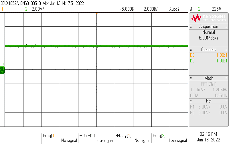
2. And the rest of the 4 pins are producing PWM pulses with a random dutycycle value, which I havent initialized anywhere in my code. All the 4 pins are producing the same dutycycle of 20 percent and frequency is around 100kHz, which is also not set by me. I have attached the images of the output generated herewith. PFA.
Figure 1. 3.3V output from the pins which needs to produce PWM pulses.
Figure 2. PWM pulses from the undesired pins having 20 percent dutycycle and 100kHz frequency.
- Mark as New
- Bookmark
- Subscribe
- Mute
- Subscribe to RSS Feed
- Permalink
- Report Inappropriate Content
Hi @HARINI_T!
The issue you are experiencing is due to a synchronization mistake. Let me explain:
You initialize the FTM with the default configuration using:
FTM_GetDefaultConfig(&ftminitialisation);
This configuration is set up with a software trigger to update the registers:
/* Software trigger will be used to update registers */
    config->pwmSyncMode = (uint32_t)kFTM_SoftwareTrigger;
Therefore, you need to provide the trigger in your code in order to update the registers.
This is because several FTM registers (including FTMx_CnV) have a buffer and cannot be directly written to when addressed by the software in order to ensure a properly synced write of the register:
“In output modes, writing to a CnV register latches the value into a buffer. A CnV register is updated with the value of its write buffer according to Registers updated from write buffers.” (p. 849 of RM).
When using:
FTM_UpdatePwmDutycycle(BOARD_FTM_BASEADDR, FTM_Channel_0, 0U, g_d0);
you are only writing the new value on the buffer, so you need to create the software trigger to write the value that is currently stored in the buffer, into the actual register. This can be done with the following function:
FTM_SetSoftwareTrigger(BOARD_FTM_BASEADDR, true);
For more information about the buffer and register synchronization requirements, please see Chapter 38.3.11 “Synchronization (FTMx_SYNC)” of the Reference Manual.
Always a pleasure to help,
Edwin.
- Mark as New
- Bookmark
- Subscribe
- Mute
- Subscribe to RSS Feed
- Permalink
- Report Inappropriate Content
Hi Edwin,
Thanks a lot for the spontaneous reply @EdwinHz. It greatly helped me in debugging the program. I tried your method and was very happy to obtain the output. Thanks again!