
- NXP Forums
- Product Forums
- General Purpose MicrocontrollersGeneral Purpose Microcontrollers
- i.MX Forumsi.MX Forums
- QorIQ Processing PlatformsQorIQ Processing Platforms
- Identification and SecurityIdentification and Security
- Power ManagementPower Management
- MCX Microcontrollers
- S32G
- S32K
- S32V
- MPC5xxx
- Other NXP Products
- Wireless Connectivity
- S12 / MagniV Microcontrollers
- Powertrain and Electrification Analog Drivers
- Sensors
- Vybrid Processors
- Digital Signal Controllers
- 8-bit Microcontrollers
- ColdFire/68K Microcontrollers and Processors
- PowerQUICC Processors
- OSBDM and TBDML
-
- Solution Forums
- Software Forums
- MCUXpresso Software and ToolsMCUXpresso Software and Tools
- CodeWarriorCodeWarrior
- MQX Software SolutionsMQX Software Solutions
- Model-Based Design Toolbox (MBDT)Model-Based Design Toolbox (MBDT)
- FreeMASTER
- eIQ Machine Learning Software
- Embedded Software and Tools Clinic
- S32 SDK
- S32 Design Studio
- Vigiles
- GUI Guider
- Zephyr Project
- Voice Technology
- Application Software Packs
- Secure Provisioning SDK (SPSDK)
- Processor Expert Software
-
- Topics
- Mobile Robotics - Drones and RoversMobile Robotics - Drones and Rovers
- NXP Training ContentNXP Training Content
- University ProgramsUniversity Programs
- Rapid IoT
- NXP Designs
- SafeAssure-Community
- OSS Security & Maintenance
- Using Our Community
-
-
- Home
- :
- General Purpose Microcontrollers
- :
- Kinetis Microcontrollers
- :
- Re: How to write SPI with MK10FN1M0VLQ12
How to write SPI with MK10FN1M0VLQ12
- Subscribe to RSS Feed
- Mark Topic as New
- Mark Topic as Read
- Float this Topic for Current User
- Bookmark
- Subscribe
- Mute
- Printer Friendly Page
- Mark as New
- Bookmark
- Subscribe
- Mute
- Subscribe to RSS Feed
- Permalink
- Report Inappropriate Content
I'm a begginer
This is my first time programming and I want to try to use MK10FN1M0VLQ12 to connect isl78600ANCZ with SPI
But I have no idea how to start.
Solved! Go to Solution.
- Mark as New
- Bookmark
- Subscribe
- Mute
- Subscribe to RSS Feed
- Permalink
- Report Inappropriate Content
Hi yu-jung,
At first, you need to learn your is178600 at first, especially the SPI communication and the control command and data, then you need to know when the is178600 is the SPI slave node, what the SPI data and wave it need, you can find details from your SPI slave datasheet:
https://www2.renesas.cn/cn/zh/doc/datasheet/isl78600.pdf
This part you must do it by yourself, or you can try to find some application note from is178600 's company.
Then, from the NXP MK10 side, you can refer to the K60 120M sample code:
Kinetis 120MHz bare metal sample code
You can find the spi code in folder: KINETIS_120MHZ_SC\build\iar\dspi
Then you just need to modify the SPI send data to your Slave's according SPI data.
Wish it helps you!
Have a great day,
Kerry
-----------------------------------------------------------------------------------------------------------------------
Note: If this post answers your question, please click the Correct Answer button. Thank you!
-----------------------------------------------------------------------------------------------------------------------
- Mark as New
- Bookmark
- Subscribe
- Mute
- Subscribe to RSS Feed
- Permalink
- Report Inappropriate Content
Hi, I am trying to configure the CAN function. I used the I-7565-H1(from ICP DAS Co.) to connect with my board. The first test, I try to use the example code to print the 0x00,0x01,0x02,0x03 on the user interface. The next test, I will try to build the buffer let CAN to get the data from the SPI. But, the first test can't work. I am wondering if there are some wrong on my code or the configuration? The following is my code and the user guide of I-7565-H1.
- Mark as New
- Bookmark
- Subscribe
- Mute
- Subscribe to RSS Feed
- Permalink
- Report Inappropriate Content
Hi yu-jung,
I am not familiar with your I-7565-H1, what I can help you is just the kinetis SPI wave is correct.
If your SPI wave is already correct, I think it is your SPI slave side commander sequence is not correct, you need to read your slave datasheet carefully.
If you have some other platform can work with your SPI slave, I suggest you use the logical analyzer to get SPI wave and the data, then in the kinetis side, write the same command, make the SPI wave is the same as your working platform, this method will help you to save the time, and this is the normal test method.
Wish it helps you!
Have a great day,
Kerry
-------------------------------------------------------------------------------
Note:
- If this post answers your question, please click the "Mark Correct" button. Thank you!
- We are following threads for 7 weeks after the last post, later replies are ignored
Please open a new thread and refer to the closed one, if you have a related question at a later point in time.
-------------------------------------------------------------------------------
- Mark as New
- Bookmark
- Subscribe
- Mute
- Subscribe to RSS Feed
- Permalink
- Report Inappropriate Content
Hi, Kerry. I already have logical analyzer to check my SPI wave. Then I also have some problem hope you can help me.
I think my CLK and CS is correct, but mosi and miso is wrong, I'm not sure what is the problem, maybe is my SPI slave side commander sequence is not correct or my code have something need to change? Hope you can give me some advice. Thank you!
Another one is "spi_outdata[0]=0xFF; //send dummy" is must write to SPI or not? I see another you answer "// don't care, just for read back data."
- Mark as New
- Bookmark
- Subscribe
- Mute
- Subscribe to RSS Feed
- Permalink
- Report Inappropriate Content
Hi yu-jung,
From your SPI wave, it seems your MOSI pin have a lot of glitch, so, please check your SPI_MOSI and SPI_MISO pin, please enable the pull up in the PORT register.
BTW, this case is really a little old, and it is already closed.
So, maybe it's better to create a new question post about it, then we can continue to help you in your new case for the deep discussion.
Wish it helps you!
Have a great day,
Kerry
-------------------------------------------------------------------------------
Note:
- If this post answers your question, please click the "Mark Correct" button. Thank you!
- We are following threads for 7 weeks after the last post, later replies are ignored
Please open a new thread and refer to the closed one, if you have a related question at a later point in time.
-------------------------------------------------------------------------------
- Mark as New
- Bookmark
- Subscribe
- Mute
- Subscribe to RSS Feed
- Permalink
- Report Inappropriate Content
Hi yu-jung,
At first, you need to learn your is178600 at first, especially the SPI communication and the control command and data, then you need to know when the is178600 is the SPI slave node, what the SPI data and wave it need, you can find details from your SPI slave datasheet:
https://www2.renesas.cn/cn/zh/doc/datasheet/isl78600.pdf
This part you must do it by yourself, or you can try to find some application note from is178600 's company.
Then, from the NXP MK10 side, you can refer to the K60 120M sample code:
Kinetis 120MHz bare metal sample code
You can find the spi code in folder: KINETIS_120MHZ_SC\build\iar\dspi
Then you just need to modify the SPI send data to your Slave's according SPI data.
Wish it helps you!
Have a great day,
Kerry
-----------------------------------------------------------------------------------------------------------------------
Note: If this post answers your question, please click the Correct Answer button. Thank you!
-----------------------------------------------------------------------------------------------------------------------
- Mark as New
- Bookmark
- Subscribe
- Mute
- Subscribe to RSS Feed
- Permalink
- Report Inappropriate Content
Do you know of any examples that use Modified Transfer Format (MCR->MTFE=1)?
I'm getting very strange results ...
- Mark as New
- Bookmark
- Subscribe
- Mute
- Subscribe to RSS Feed
- Permalink
- Report Inappropriate Content
Hi chris_f,
If you have the question, please create your own new question post, then we will help you in the new question post.
Best Regards,
Kerry
- Mark as New
- Bookmark
- Subscribe
- Mute
- Subscribe to RSS Feed
- Permalink
- Report Inappropriate Content
Hi Kerry,
Sorry for spamming this question but I've had no responses to my question here: https://community.nxp.com/thread/516859
Best Regards
Chris
- Mark as New
- Bookmark
- Subscribe
- Mute
- Subscribe to RSS Feed
- Permalink
- Report Inappropriate Content
Hi chris_f,
OK, I will take your new question case, and will reply you tomorrow, please keep patient, thank you!
Best Regards,
Kerry
- Mark as New
- Bookmark
- Subscribe
- Mute
- Subscribe to RSS Feed
- Permalink
- Report Inappropriate Content
Thank you for your help, I try to use another example code to test my SPI without use DMA,
But I found the CS have no change on my Oscilloscope, it should be a line, but not.
I don't know what happend, maybe I forgot to do some important configurations?
The following is my code:
void spiinit();
/*****************************/
int main(void)
{
PE_low_level_init();
spiinit();
for(;;){
SPI0_MCR &= ~(SPI_MCR_HALT_MASK | SPI_MCR_FRZ_MASK);
SPI0_SR &= ~SPI_SR_EOQF_MASK;
SPI0_PUSHR = (SPI_PUSHR_EOQ_MASK | SPI_PUSHR_PCS(1) | 0x01);
while(!(SPI0_SR | SPI_SR_TCF_MASK));
SPI0_SR |= SPI_SR_TCF_MASK | SPI_SR_EOQF_MASK;
SPI0_MCR |= SPI_MCR_HALT_MASK;
}
return 0;
]
/*=============== Functions declaration ====================*/
/***********************************/
void spiinit(){
//Clock settings
SIM_SCGC5 |= SIM_SCGC6_DSPI0_MASK;
SIM_SCGC6 |= SIM_SCGC5_PORTD_MASK;
//Port Settings
/* PORTD_PCR19: ISF=0,MUX=2 */
PORTD_PCR19 = (uint32_t)((PORTD_PCR19 & (uint32_t)~(uint32_t)(
PORT_PCR_ISF_MASK |
PORT_PCR_MUX(0x05)
)) | (uint32_t)(
PORT_PCR_MUX(0x02)
));
/* PORTD_PCR18: ISF=0,MUX=2 */
PORTD_PCR18 = (uint32_t)((PORTD_PCR18 & (uint32_t)~(uint32_t)(
PORT_PCR_ISF_MASK |
PORT_PCR_MUX(0x05)
)) | (uint32_t)(
PORT_PCR_MUX(0x02)
));
/* PORTD_PCR17: ISF=0,MUX=2 */
PORTD_PCR17 = (uint32_t)((PORTD_PCR17 & (uint32_t)~(uint32_t)(
PORT_PCR_ISF_MASK |
PORT_PCR_MUX(0x05)
)) | (uint32_t)(
PORT_PCR_MUX(0x02)
));
/* PORTD_PCR16: ISF=0,MUX=2 */
PORTD_PCR16 = (uint32_t)((PORTD_PCR16 & (uint32_t)~(uint32_t)(
PORT_PCR_ISF_MASK |
PORT_PCR_MUX(0x05)
)) | (uint32_t)(
PORT_PCR_MUX(0x02)
));
SPI0_RSER = 0;
SPI0_TCR = 0;
SPI0_SR = (SPI_SR_TCF_MASK | SPI_SR_TXRXS_MASK | SPI_SR_EOQF_MASK | SPI_SR_TFUF_MASK | SPI_SR_TFFF_MASK | SPI_SR_RFOF_MASK | SPI_SR_RFDF_MASK);
SPI0_MCR =0;
SPI0_MCR = SPI_MCR_MSTR_MASK | (0 << SPI_MCR_FRZ_SHIFT) | SPI_MCR_PCSIS(1) | SPI_MCR_DCONF(0) | (1 << SPI_MCR_DIS_TXF_SHIFT) | (1 << SPI_MCR_DIS_RXF_SHIFT) | (1 << SPI_MCR_CLR_TXF_SHIFT) | (1 << SPI_MCR_CLR_RXF_SHIFT) | (1 << SPI_MCR_HALT_SHIFT);
SPI0_CTAR0 = 0;
SPI0_CTAR0 |= (0 << SPI_CTAR_DBR_SHIFT) | SPI_CTAR_FMSZ(7) | (0 << SPI_CTAR_CPOL_SHIFT) | (0 << SPI_CTAR_CPHA_SHIFT) | (0 << SPI_CTAR_LSBFE_SHIFT) | SPI_CTAR_PCSSCK(0) | SPI_CTAR_CSSCK(1) | SPI_CTAR_ASC(0) | SPI_CTAR_PDT(3) | SPI_CTAR_DT(5) | SPI_CTAR_BR(1);
}
/**********************************************/
/* END main */
- Mark as New
- Bookmark
- Subscribe
- Mute
- Subscribe to RSS Feed
- Permalink
- Report Inappropriate Content
Hi yu-jung Chuang,
Please tell me what the detail pins you want to use in the K10, take an example, SPI_CS is PTxx? SSEL, MOSI, MISO is what pin?
Then, I will help you to check it.
Have a great day,
Kerry
-----------------------------------------------------------------------------------------------------------------------
Note: If this post answers your question, please click the Correct Answer button. Thank you!
-----------------------------------------------------------------------------------------------------------------------
- Mark as New
- Bookmark
- Subscribe
- Mute
- Subscribe to RSS Feed
- Permalink
- Report Inappropriate Content
- Mark as New
- Bookmark
- Subscribe
- Mute
- Subscribe to RSS Feed
- Permalink
- Report Inappropriate Content
Hi yu-jung,
I am afraid I don't have time to help you do the test now.
from tomorrow, I will on our Chinese Spring Festival, I will back on February 11th.
So, I will reply you on 2019 February 11th. If you are in a hurry, you can create the new case, then my other colleague also will help you!
Thanks a lot for your understanding and sorry for the inconvenience I bring you!
But from my own opinion, you can enable the PORT pull up in the pinmux, then try it again.
Have a great day,
Kerry
-----------------------------------------------------------------------------------------------------------------------
Note: If this post answers your question, please click the Correct Answer button. Thank you!
-----------------------------------------------------------------------------------------------------------------------
- Mark as New
- Bookmark
- Subscribe
- Mute
- Subscribe to RSS Feed
- Permalink
- Report Inappropriate Content
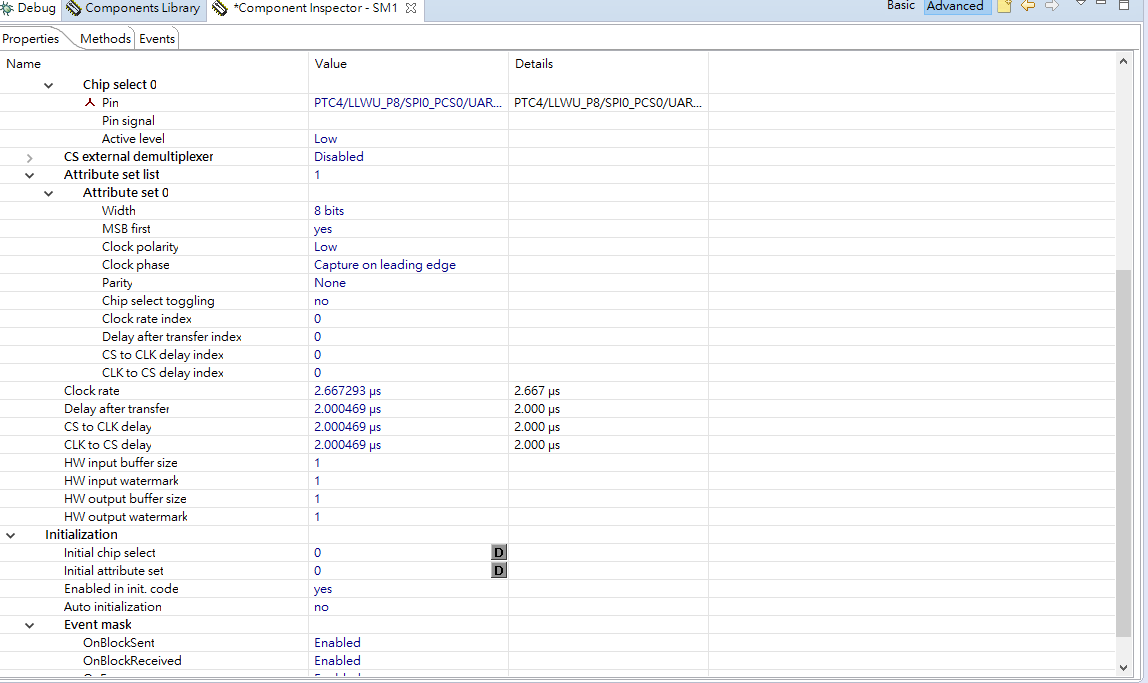
Hi, Kerry Zhou, I already set up the SPI function. This is working. But I'm not sure is it correct or not?? Because the waveform of the SCK and CS is a little weird. The following is my SPI code. I using GPIO for SPI CS. On the other hand, I want to use the CAN function to get the data from the SPI and to print it on my screen to moniter this data. But I'm not sure can we transform it directly or we should use DMA function so the CAN can get the data from the buffer??
- Mark as New
- Bookmark
- Subscribe
- Mute
- Subscribe to RSS Feed
- Permalink
- Report Inappropriate Content
Hi yu-jung,
Your CS pin wave is not correct, the CS should pull low before you transfer the SPI data, after you finish the SPI data transfer, you can pull up it again.
So, please check your CS pin control, the gpio CS pin should pull up after the SPI data is transfered, you need to wait it.
After the SPI data printf to the CAN, you can put the SPI data in the RAM buffer, then you can send that SPI data in the RAM buffer to your CAN buffer to test.
Wish it helps you!
If you still have question about, please let me know.
Have a great day,
Kerry
-------------------------------------------------------------------------------
Note:
- If this post answers your question, please click the "Mark Correct" button. Thank you!
- We are following threads for 7 weeks after the last post, later replies are ignored
Please open a new thread and refer to the closed one, if you have a related question at a later point in time.
-------------------------------------------------------------------------------
- Mark as New
- Bookmark
- Subscribe
- Mute
- Subscribe to RSS Feed
- Permalink
- Report Inappropriate Content
Hello Kerry Zhou,
Thank you for your answer.
I think the code is correct. Maybe there have something wrong in my SPI configuration .
I already watch the datasheet and user guide, but i have no idea how to decide to configure the clock rate and the delay.
Once,CS the wave seems correct ,like the following figure1,but i think it maybe have to seems like the example of ISL78600 datasheet , the wave should be very close like figure2 that the CS should be pull high after the system send 8 bits then CS pull down and keep to send 8 bits.
But now i have no idea how to solve the problem.
- Mark as New
- Bookmark
- Subscribe
- Mute
- Subscribe to RSS Feed
- Permalink
- Report Inappropriate Content
Hi Yu-jung,
Yes, now, the new attached SPI wave is correct, because the CS is pulled low before you send the data, after the data is completed, you pull up the CS pin.
Now, if you still can't do the communication with your external component, I think you need to check the detail SPI data, and the SPI CPHA and the CPOL should be the same as your SPI slave side.
I suggest you find a Logic analyzer to test the SPI bus wave, and the according data, whether the SPI data meet your external SPI slave demand.
Have a great day,
Kerry
-------------------------------------------------------------------------------
Note:
- If this post answers your question, please click the "Mark Correct" button. Thank you!
- We are following threads for 7 weeks after the last post, later replies are ignored
Please open a new thread and refer to the closed one, if you have a related question at a later point in time.
-------------------------------------------------------------------------------