
- NXP Forums
- Product Forums
- General Purpose MicrocontrollersGeneral Purpose Microcontrollers
- i.MX Forumsi.MX Forums
- QorIQ Processing PlatformsQorIQ Processing Platforms
- Identification and SecurityIdentification and Security
- Power ManagementPower Management
- MCX Microcontrollers
- S32G
- S32K
- S32V
- MPC5xxx
- Other NXP Products
- Wireless Connectivity
- S12 / MagniV Microcontrollers
- Powertrain and Electrification Analog Drivers
- Sensors
- Vybrid Processors
- Digital Signal Controllers
- 8-bit Microcontrollers
- ColdFire/68K Microcontrollers and Processors
- PowerQUICC Processors
- OSBDM and TBDML
-
- Solution Forums
- Software Forums
- MCUXpresso Software and ToolsMCUXpresso Software and Tools
- CodeWarriorCodeWarrior
- MQX Software SolutionsMQX Software Solutions
- Model-Based Design Toolbox (MBDT)Model-Based Design Toolbox (MBDT)
- FreeMASTER
- eIQ Machine Learning Software
- Embedded Software and Tools Clinic
- S32 SDK
- S32 Design Studio
- Vigiles
- GUI Guider
- Zephyr Project
- Voice Technology
- Application Software Packs
- Secure Provisioning SDK (SPSDK)
- Processor Expert Software
-
- Topics
- Mobile Robotics - Drones and RoversMobile Robotics - Drones and Rovers
- NXP Training ContentNXP Training Content
- University ProgramsUniversity Programs
- Rapid IoT
- NXP Designs
- SafeAssure-Community
- OSS Security & Maintenance
- Using Our Community
-
-
- Home
- :
- University Programs
- :
- University Programs Knowledge Base
- :
- Data acquisition system for Kinetis K Family
Data acquisition system for Kinetis K Family
- Subscribe to RSS Feed
- Mark as New
- Mark as Read
- Bookmark
- Subscribe
- Printer Friendly Page
- Report Inappropriate Content
Data acquisition system for Kinetis K Family
Data acquisition system for Kinetis K Family
Data acquisition system for Kinetis K Family
Author : Mauro Padin (Student)
Supervisors : Professor Daniel A. Jacoby, Juan Pablo Vega (Teacher Assistant)
Summary:
This project is based on the FRDM-K64F board, a HC-05 Bluetooth module, and a smartphone. In this application, an analog signal is sampled and transmitted wirelessly to a smartphone, using an external Bluetooth module, where it is displayed. The complete CodeWarrior C code and MIT App Inventor code can be found in the .zip file.
System Structure
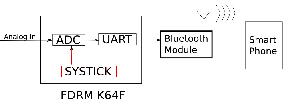
SysTick Module: Periodically triggers ADC conversions and UART transmissions.
ADC Module: Samples the analog signal and manages the ADC input buffer.
UART Module: Manages the UART output buffer and transmits the digitized data.
Bluetooth Module: When connected, wirelessly transmits the data coming from the UART module.
Smartphone App: Handles Bluetooth connection, receives the digitized data and manages the display.
Software Structure
A project template is provided to the students in order to establish a simple, and easy, program organization for the duration of the course. A portion of the template was built with the help of the Processor Expert so that, later on, the students would be able to understand its structure and limitations, and transition to this new tool. A wrapper was built around this auto-generated code and the resulting function, void __LDM_init (void), is to be used at the very beginning of the project given. This function mainly configures internal processor registers related to clock configuration.
The project is composed of separate files for each hardware and software module:
- The template is composed of four files: LDM.c/h, main.c, and misc.h.
- The application is found in: App.c/h
- RTI, ADC, UART, LED Drivers are defined in: RTI.c/h, adc.c/h, uart.c/h, and LED.c/h.
The basic Driver structure consists of a void DRV_init(void) initialization, a set of void DRV_x_ISR(void) interrupt handlers, a set of void DRV_x_PISR(void) periodic interrupt handlers, and a set of void DRV_x services function. Only the initialization function is mandatory, the others being optional and dependent on the driver purpose. Service functions are interfaces between the application and the Driver and do not necessarily access any subjacent hardware. Indeed, this Driver structure can be nested and thus not handle any hardware at all. When a Driver function does access hardware, it is recommended to further use a Hardware Abstraction Layer to enhance productivity and improve portability.
Extracts of the system
As an example of the Driver Structure, the LED Driver is described below:
init
void LED_init (void)
ISR
N/A
PISR
void LED_PISR (void)
Services
void LED_write (color_t color, bool value)
void LED_set (color_t color)
void LED_clear (color_t color)
void LED_toggle (color_t color)
The entire application is interrupt driven, so that only initialization are necessary and the run loop is empty:
void App_init(void)
{
LED_init(); // LED driver init function
uart_init(); // UART driver init function
adc_init(); // ADC driver init function
RTI_init(); // RTI driver init function
}
void App_run(void) { }
Hardware interrupts are not serviced in their specific handler but referred to external handlers for readability and organization. The SysTick interrupt handler is composed of a ISR and a Service:
ISR_t SysTick_Handler(void)
{
LED_isr code
ADC_conv code
}
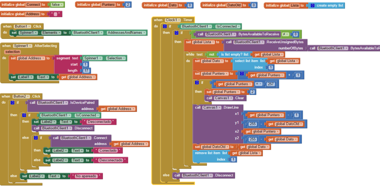
The code for the smartphone side is depicted below:
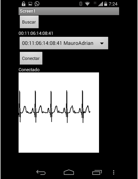
Finally, a screenshot of the result:
Original Attachment has been moved to: -ADC-bluetooth-TP6.zip